23
34-55 08/14
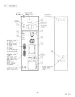
A1-A2:
Used to activate a remote alarm signaling shutdown of combustion control.
Provides a maximum 10 amp relay contact closure when the flame safeguard terminates combustion due to a
tripped safety interlock (i.e.: air proving switch high limit switch, low water flow switch or flame sensor, etc.).
Options Required - Consult Factory.
P1-P2:
Activates remote equipment and requires confirmation signal back to the appliance.
Provides a maximum 10-amp relay contact closure to activate a remote device (i.e.: mechanical room air louvers,
draft inducer or power vent, etc.). The remote device must send return signal via proving switch to confirming
proper operation to terminals C1-C2, prior to the appliance being able to energize.
Options Required - Consult
Factory.
C1-C2:
Used for proving operation of remote device.
Terminals are wired to a proving switch on a remote device such as a power venter. When relay closes, circuit
from C1 to C2 is completed and appliance controls are enabled. This appliance ships form the factory with jumper
between terminals.
T1-T2:
Used for external modulation control.
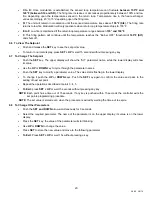
To connect external modulation control, disconnect and cap the blue wire connected to terminal T2 and connect
the external modulating signal to terminals T1 (positive) and T2 (negative).
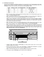
10.5 Outdoor Reset (requires option for outdoor reset through the TempTrac control, code OUTRC)
The TempTrac control is capable of an outdoor reset function independent of an external control. The option
includes a third sensing probe and activates the probe in the TempTrac. The outdoor reset function overrides the
St1 setting when the outdoor air temperature falls to the tt setting. St1 is increased in increments through the range
established by rr2. When the outdoor air temperature falls to the bottom of the rr2 range, the St1 setting will have
been adjusted upward by the amount of the rr1 value.
(See Outdoor Reset Manual #34-400.6 for full
description.)
•
Factory Default Settings - The values of the Outdoor Reset and Warm Weather Shutdown functions in the
TempTrac control’s parameter Pr2 menu can be changed from the factory default values listed below:
•
Outside Air Temperature Sensor Installation - The wire leads for the outdoor sensor should be connected to the
TempTrac control located on the control panel of the boiler. Use sensor P/N 102163.
•
Pass the temperature sensing probe through the wall to the building's exterior. Use sound construction techniques
to create and insulate the wall penetration. To operate properly, the sensor must be located away from direct
sunlight and protected from the weather. The length of the wire leads on the thermister is 25 feet. If more wire
is needed, it is admissible to splice 22-gage, multi-strand copper wire into the thermister coil. (Thermister
probe should be protected with suitable outdoor cover.)
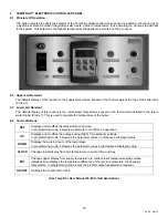
10.6 Riverside Hydronics® ONTRAC® Boiler Management System (BMS)
The OnTrac is a separate multiple boiler control designed to coordinate the operation of multiple boilers using
TempTrac controls. This section will briefly summarize the controller’s capabilities and features.
(See ONTRAC
Programming Manual #34-152 and Wiring Guide #34-151 for full description.)
−
Controls up to 20 boilers (more with expansion card).
−
PID control with full-color, touch-screen interface.
−
Basic functions include lead-lag outdoor reset, nighttime setback and isolation valve control.
Display Parameter
Description Value
St1
Temperature at the return boiler loop that activates /deactivates boiler firing
165° F
tt
Outdoor air temperature where outdoor reset is activated and deactivated
30° F
rr2
Outdoor air temperature range through which St1 setting will be adjusted
-20° F
rr1
Maximum increase of St1 setting when outdoor reset is activated
10° F
tt2
Outdoor air temperature where boiler is de-energized
100° F
Ht2
Differential from tt2 required to reenergize the boiler
-10° F


