7
34-55 08/14
4
GENERAL PIPING GUIDELINES
Consult factory for piping of hybrid boiler systems that contain both condensing and non-condensing boilers.
4.1 Inlet and Outlet Connections
The connection to the unit marked “Inlet” on the header connects to the return from the system (water to be heated).
The connection on the header marked “Outlet” connects to the supply side of the system (hot water out of the unit).
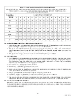
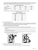
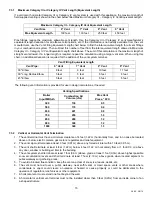
4.2 Supply and Return Piping (For Non-hybrid Boiler System)
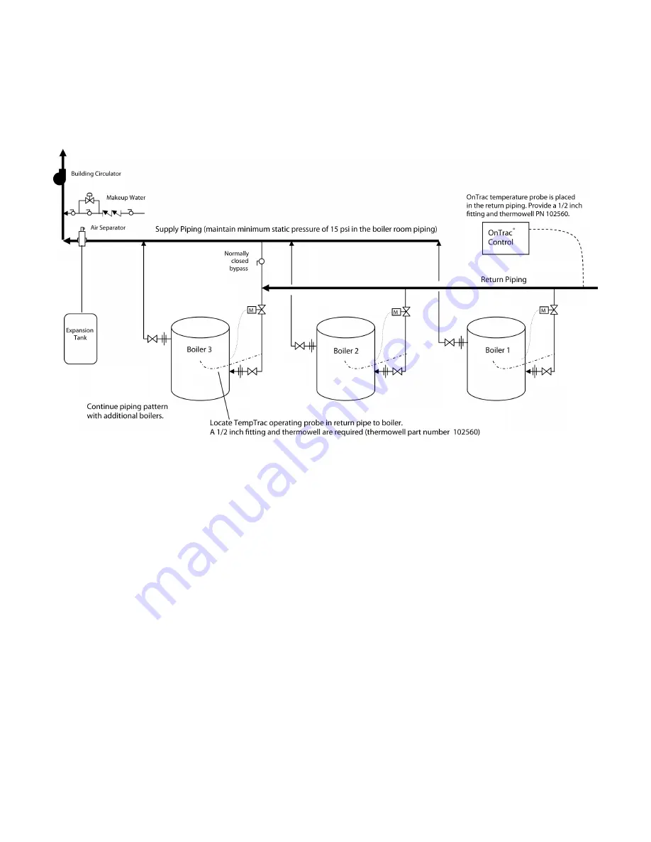
NOTE: For motorized isolation valves on each boiler’s inlet piping:
−
In constant flow building loops, motorized isolation valves must NOT be used.
−
In buildings with variable flow pumping systems on the boiler loop, motorized isolation valves may be
recommended. Building flow may have to be limited to only the firing boilers during periods of low building heat
demand to prevent temperature from reaching the boiler’s operating limit.
−
It is recommended that the OnTrac multiple boiler control be used to control these valves. Consult your Riverside
Hydronics representative for design assistance.
4.3 Temperature Control Sensor
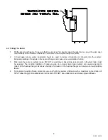
The Temperature Control Sensor is coiled and secured to the control enclosure along with the Sensor Thermal Well.
IMPORTANT
: The thermal well must be installed in the return plumbing 1 to 4 feet from the return connection on the
boiler. The sensor should then be inserted into the thermal well along with thermal conductive paste. Use the plastic
threaded plug to secure the sensor in place.


