background image


10

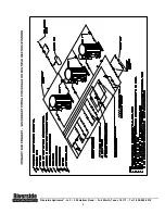
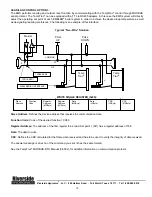
LEAD/LAG CONTROL OPTION 3:  

The EMS performs lead-lag and outdoor reset function by communicating with the TempTrac

®

 control through MODBUS 

serial protocol. The TempTrac

®

 can be equipped with a TTL to RS485 adapter. In this case the EMS system will directly 

adjust the operating set point of each EMBLEM

®

 boiler system in order to achieve the desired loop temperature as well 

as designating lead-lag preference. The following is an example of this interface: 


Typical “Two-Wire” Solution


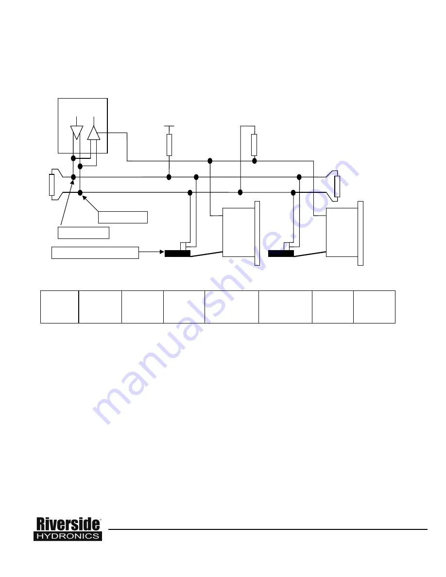
WRITE SINGLE REGISTER (0x06): 


Slave Address

: Defines the device address that receives the communication data. 


Function Code

: Code of the desired function = 0X06 


Register Address

: The address of the first register to be read. Set point 1 (St1) has a register address of 768 


Data: 

The data to write  


CRC

: Defines the CRC calculated for the frame data received and has to be used to verify the integrity of data received. 

 
The answer message is an echo of the command you sent (it has the same format). 
 
See the TempTrac

®

 MODBUS-RTU Manual (34-502), for addition information on communication protocol. 


Riverside Hydronics

®

, LLC  -  990 Haltom Road  -  Fort Worth, Texas  76117  -  Tel 1-800-990-5918 

Slave 
Address 

Function 
Code 

Register 
Address 
(MSByte) 

Register 
Address 
(LSByte) 

Data 
(MSByte) 

Data 
(LSByte) 

CRC 
(LSByte) 

CRC 
(MSByte) 

Master 


Temp
Trac

®


Temp
Trac

®


D0 

D1


COMMON


L

L

-

+

TXD0&RXD0


TXD1& RXD1 

-

+

PULL 

DOWN 

PULL 

UP 

XJ485 SERIAL INTERFACE 

Summary of Contents for Emblem

Page 1: ...structions must be given to the equipment user or left near the appliance Refer to I M documents 34 50 34 501 and 34 502 for additional important information SPECIAL INSTRUCTIONS TO THE OWNER Retain t...

Page 2: ...res are high the EMBLEM system engages a non condensing boiler to supplement heat output Although non condensing the secondary boiler in the EMBLEM system still operates at relatively high efficiency...

Page 3: ...n from the system water to be heated to the Inlet of the EPV boiler Connect the Outlet to the supply side of the system hot water out of the unit FILLING THE UNIT 1 Fill the system with water To be su...

Page 4: ...1 St1 parameter is the first to be displayed Press the Set key again and adjustment is enabled Use the arrow keys to adjust the set point 1 to the desired system temperature and press the set key agai...

Page 5: ...the inherent flexibility of the EMBLEM system The Primary Only System is generally not applied with modern PRIMERA boiler systems due to the need to maintain a constant flow rate through the boiler Th...

Page 6: ...6 Riverside Hydronics LLC 990 Haltom Road Fort Worth Texas 76117 Tel 1 800 990 5918...

Page 7: ...t always the case Untreated make up water is a leading cause for failures of hat water boilers Provisions must be made for properly introducing metering and treating make up water Below are some consi...

Page 8: ...he E series parameters are divided into 10 minute increments The E1 parameter is Sunday The S series parameters are the ending point for the programmed shift in set point The S series parameters are d...

Page 9: ...1 160 E2 0 0 S2 6 0 Sb2 25 LEAD LAG CONTROL OPTION 2 The lead lag and outdoor reset function is managed by a third party Boiler Management System BMS or building Energy Management System EMS This mann...

Page 10: ...ata Function Code Code of the desired function 0X06 Register Address The address of the first register to be read Set point 1 St1 has a register address of 768 Data The data to write CRC Defines the C...

Reviews: