

EMBLEM
®
OVERVIEW
- The EMBLEM
®
is a boiler heating system that interconnects a condensing boiler
with a non-condensing boiler and uses a control algorithm to fire each or both boilers as necessary to meet
the building heat requirements while providing maximum efficiency throughout the heating season.
During periods of low to medium building heat demand, whether seasonal or occupancy driven or both,
significant fuel savings can be realized by reducing the boiler loop temperature. A condensing boiler offers
the greatest value to building owners when loop temperatures are low enough (< 130°F) to allow the water
vapor in flue products to condense inside the boiler where the latent energy (heat) of condensation is
captured. The condensing boiler in the EMBLEM
®
system is sized to meet the output requirement during low
to medium heat demand. Because it captures the latent heat released during condensation, thermal
efficiency ranges from 93% to 99% depending upon return water temperature and firing rate. A modular
arrangement of non-condensing boilers, even with modulation, is unable to capture this heat and, as a
result, is less efficient.
During periods of higher building heat demand, loop temperatures are normally elevated and are too high to
allow condensing of flue gases. As a result, firing additional condensing boilers with loop temperatures
greater than 130°F offers little efficiency advantage compared to non-condensing boilers. When heat
demand and loop temperatures are high, the EMBLEM
®
system engages a non-condensing boiler to
supplement heat output. Although non-condensing, the secondary boiler in the EMBLEM
®
system still
operates at relatively high efficiency of 85%. The combined output of each boiler in the EMBLEM
®
system
meets building demand during the coldest days of the heating season.
Over the heating season, the average output of a boiler system is approximately 35% of its total heating
capacity. Such oversizing is unavoidable because of the few unusually cold days when maximum heating
system output is essential to building comfort. EMBLEM
®
intelligently combines boilers of different
efficiencies and fires those boilers when appropriate during the heating season to meet all heat
requirements and maximize fuel savings for the building owner.
Riverside Hydronics
®
, LLC - 990 Haltom Road - Fort Worth, Texas 76117 - Tel 1-800-990-5918
WARNING: Improper installation, adjustment, alteration, service or maintenance can cause property
damage, personal injury, exposure to hazardous materials or loss of life. Refer to and follow the information
contained in this manual, the PRIMERA
®
I&M, the EPV
®
I&M, all provided documents labels and warnings.
Installation and service must be performed by a qualified installer, service agency or the gas supplier, who
must read and follow all supplied instructions before installing, servicing or removing these appliances.
CONTENTS
TOPIC
PAGE
TOPIC
PAGE
General Safety Warnings and Codes
1 & 2
Heating Boiler System Piping
5
EMBLEM
®
Overview
2
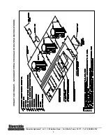
Piping Illustration
6
Electrical and Water Connections
3
Water Considerations
7
Operation and General Information
4
Lead/Lag Systems
8-10
General Information
4


