
4
OPERATION
LOW WATER CUTOFF -
Proper function of the low water cutoffs should be verified every six months. See individual
boiler Installation & Maintenance manuals for details.
OPERATING TEMPERATURE CONTROL -
An adjustable digital operating control, TempTrac
®
,
is located in the front
control panel of the PRIMERA
®
boiler. This control uses a remote sensing bulb mounted in the outlet fitting of the EPV
®
boiler. The function of this control is specially designed to coordinate the operation as well a firing rate of both boilers in
order to match the heat load of the system while maximizing the fuel efficiency. Do not attempt to alter control system
parameters without factory direction. Improper adjustments could disable operation.
The sequence of control logic could be as follows:
1. System heat demand is at a minimum, the EPV
®
boiler fires at the lowest firing rate, periodically cycling. This
condition is the most efficient operation.
2. System demand increases and the TempTrac
®
will stage the EPV
®
boiler between the lowest firing rate and the
highest firing rate, in order to match heat delivery to system heat demand. This condition continues to operate at
a high efficiency.
3. System heat demand further increases as system approaches peak heat demand. The TempTrac
®
now enables
the
PRIMERA
®
boiler and simultaneously reduces the firing rate of the EPV
®
boiler to it lowest firing rate. The
TempTrac
®
will now modulate the
PRIMERA
®
boiler between its lowest and highest firing rate in order to
precisely match the system heat demand.
4. System heat demand now reaches the peak heat demand and the TempTrac
®
may now enable the EPV
®
boiler
as well. The TempTrac
®
is able to simultaneously modulate the
PRIMERA
®
boiler and stage the EPV
®
boiler in
order to respond to this peak demand.
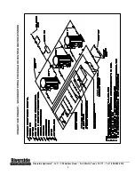
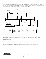
The diagram titled “EMBLEM
®
Control Logic” illustrates the operation of this system at a set-point of 155°F.
To adjust the set point of the TempTrac
®
to deliver the desired water temperature, press and release the
Set
key on the face of
the control. Set-point 1
(St1)
parameter is the first to be displayed. Press the
Set
key again and adjustment is enabled. Use
the arrow keys to adjust the set-point 1 to the desired system temperature and press the
set
key again to lock it in.
DO NOT
change the other set-points in this menu.
GENERAL INFORMATION
RELIEF VALVE
- Both heating boilers are normally supplied with a pressure only relief valve(s) sized in accordance with
the ASME Boiler and Pressure Vessel Code, Section IV; 150 psig/250 °F maximum.
Caution
: Do not install a reducing coupling, valve or other restriction in the relief valve(s) discharge line. The discharge
line shall allow complete drainage of the valve and line. Relief valves should be manually operated at least once a year.
WARNING: To prevent burns caused by hot water discharge and water damage, the discharge from both relief
valves must be piped to a suitable floor drain for disposal when relief occurs. Avoid contact with hot discharge
water.
THERMAL EXPANSION -
A relief valve that discharges periodically may be due to thermal expansion in a closed
system. This system must be provided with means to control expansion. Contact a boiler or plumbing professional to
resolve this situation. Do not plug the relief valve.
AUTOMATIC OVERRIDE SWITCH –
This 2 position switch is located on the main power disconnect panel. In the event that a
failure of the electronic temperature control occurs or the
PRIMERA
®
boiler is temporarily removed from service, the automatic
override switch can be set Manual Override, allowing the EPV
®
boiler to function independently of the EMBLEM
®
control
system.
HIGH WATER TEMPERATURE LIMIT CONTROL
– Both boilers are equipped with adjustable limit and high limit
controls to control the maximum discharge water temperature. (See: Individual boiler Installation & Maintenance
manuals for additional details about temperature limits).
WARNING: Turn off all electrical service to the appliance when accessing the limit or high limit controls located
inside the electrical enclosures. If the electrical service is not turned off and these terminals are touched, a
dangerous shock causing personal injury or loss of life could occur
.
Riverside Hydronics
®
, LLC - 990 Haltom Road - Fort Worth, Texas 76117 - Tel 1-800-990-5918