5
SPECIAL DESIGN APPLICATIONS
The EMBLEM
®
boiler system, when used in connection with a refrigeration system, must be installed so the chilled
medium is piped in parallel with the boiler with appropriate valves to prevent the chilled medium from entering the boiler.
The boiler piping system of the EMBLEM
®
(when connected to heating coils located in air handling units where they may
be exposed to refrigerated air circulation) must be equipped with flow control valves or other automatic means to prevent
gravity circulation of the boiler water during the cooling cycle.
PERFORMANCE DATA
The EMBLEM
®
boiler system is capable of operating with very low flow rates due to the water buffer contained in the
EPV
®
boiler. It is recommended however that when variable speed pumps are applied, the minimum flow rate should be
sufficient to promote fast accurate response to system demands.
The EMBLEM
®
boiler system is also capable of operating with very low return temperatures. It is recommended in fact
the return temperature be as low as possible in order to maximize the efficiency of the system.
MAINTENANCE
See individual boiler Installation & Maintenance manuals for details about product maintenance.
WARNING: When servicing the controls, use exact, Factory authorized, replacement parts and label all wires
prior to disconnection. Verify proper operation after servicing. Incorrect parts substitution and wiring errors
can cause damage, improper operation, fire, carbon monoxide and other unexpected and unsafe conditions
that could result in fire, injury or death.
HEATING BOILER SYSTEM PIPING:
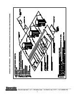
The design document on the following page illustrates examples of both a primary only and a primary – secondary
hydronic system for single or multiple boiler systems. This is intended as a general guide for use with the EMBLEM
®
systems. There are many other layout combinations which are not shown but could be adopted due to the inherent
flexibility of the
EMBLEM
®
system.
The
Primary Only System
is generally not applied with modern
PRIMERA
®
boiler systems, due to the need to maintain
a constant flow rate through the boiler. The cost saving associated with these system can only be realized with the
application of a medium to high mass boiler. The use of VFD pumping has improved functionality of primary only
systems but has further increased the risk to
PRIMERA
®
boiler systems. The EMBLEM
®
is well suited for the primary
only system.
The
Primary – Secondary System
most commonly applied to today due to the desire to control the operational
conditions of the boiler loop separately from the secondary building loop. This system is also more reliably applied when
heating systems become too large to adequately maintain the proper flow rates and temperature drops across the
individual heating zones.
The following recommendation should be considered when designing both systems:
•
Always attempt to apply reverse return piping method to help equalize water flow and simplify balancing of the
circuits.
•
Centrifugal system circulating pumps are shown. Circulating pumps should be electrically interlocked with the
boiler control circuit. The boiler should not fire unless the circulating pumps are running. In the case of VFD
pumping some minimums threshold of flow should be established and likewise interlocked with the boiler.
•
Use balancing valves in the supply lines from each boiler to the pumps in order to help equalize or portion the
flow through the boilers.
•
A make-up water meter must be installed in any raw water feed to the system.
•
A means for introducing chemicals to the system water must be provided.
•
One expansion tank for multiple boilers is typically sufficient when sized properly.
•
A (BMS) boiler management system with Lead/Lag functionality should be used for systems with multiple
boilers.
•
When using multiple boilers it is recommended that a motorized flow control valve be used in the inlet and
controlled by the boiler demand or BMS.
Riverside Hydronics
®
, LLC - 990 Haltom Road - Fort Worth, Texas 76117 - Tel 1-800-990-5918


