


8
A Lead/Lag system sequences the on-off firing of multiple boilers to meet the system load demand and equalize run
time for all the boilers in a system.
The key to the design of a lead/lag control in a hot water system is the control intelligence to react to changes in system
load which are inherently slow without over reacting. The change in boiler output does not immediately result in a
change in overall system temperature. The control system must be designed to take into account the lag times and allow
for fine tuning.
The TempTrac
®
control is designed to optimize the operation of the EMBLEM
®
system in order to provide the maximum
efficiency of operation. When interfacing a Lead/Lag system with multiple EMBLEM
®
systems
DO NOT
attempt to
interrupt the independent operation of this control. There are three options on the following page which will allow
Lead/Lag and Outdoor Reset control of the EMBLEM
®
system, while maintaining optimum efficiency.
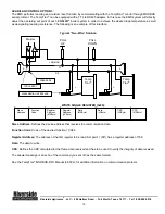
LEAD/LAG CONTROL OPTION 1: (Recommended)
The lead-lag and outdoor-reset control is accomplished by the on-board TempTrac
®
controls. The TempTrac
®
control
has a 7day real time clock which in conjunction with a programmable set-back schedule will alternately reduce the
control set-point by a programmed set-back temperature. The following is an example of a 3 boiler lead-lag schedule:
Objective
: Balance operational time evenly between all EMBLEM
®
boiler systems.
Parameters
: E1-E7, S1-S7, Sb1-Sb7
•
The E series parameters are the starting point for the programmed shift in set point. The E series
parameters are divided into 10 minute increments. The E1 parameter is Sunday.
•
The S series parameters are the ending point for the programmed shift in set point. The S series
parameters are divided into 10 minute increments. The S1 parameter is Sunday.
•
The Sb series parameters are the shift in set point imposed for the time period defined by E and S. The
shift in set point can be (-40Fto40F). The Sb1 is Sunday.
Programming
: The TempTrac
®
boiler control located on the
PRIMERA
®
allows for one button access to this
menu. Hold down the up button
ES
until E1 appears in the top display. The up/down arrow buttons will now
scroll through this menu. When you have reached the desired parameter, push the set button
in order to
enable adjustment and the up/down buttons to change the set point. Push the set button to lock in the value.
See the TempTrac
®
Service & Setup Manual (34-81), for addition information on programming.
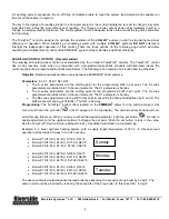
Example: A 3 boiler hydronic heating system, with a supply target temperature of 165 F. In this case lead
operation will be divided 3 ways in to a 24 hour day.
•
Boiler #1 St1=160, E1=0.0, S1=8.0, Sb1=5
•
Boiler #2 St1=160, E1=8.0, S1=16.0, Sb1=5
•
Boiler #3 St1=160, E1=16.0 S1=24.0,Sb1=5
•
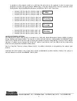
Boiler #2 St1=160, E2=0.0, S2=8.0, Sb2=5
•
Boiler #3 St1=160, E2=8.0, S2=16.0, Sb2=5
•
Boiler #1 St1=160, E2=16.0, S2=24.0,Sb2=5
•
Boiler #3 St1=160, E3=0.0, S3=8.0, Sb3=5
•
Boiler #1 St1=160, E3=8.0, S3=16.0, Sb3=5
•
Boiler #1 St1=160, E3=16.0, S3=24.0,Sb3=5
The above example would designate the lead boiler by advancing the set point of one boiler by 5 deg F. The
same result could be produced by reducing the set points of the 2 lag boiler. In this case Sb1= -5 deg F.
Riverside Hydronics
®
, LLC - 990 Haltom Road - Fort Worth, Texas 76117 - Tel 1-800-990-5918
Sunday
Monday
Tuesday


