background image


34-1161  05/17


HeatS

tation™


CONDENSING WATER BOILER


INSTALLATION & MAINTENANCE MANUAL


MODELS HS (1000, 1250, 1500, 1750, 2000) 


Installation and service must be performed by a qualified service installer, service agency or the gas supplier. 


IMPORTANT:

 THIS MANUAL CONTAINS INFORMATION REQUIRED FOR INSTALLATION, OPERATION AND MAINTENANCE 

OF  THIS  EQUIPMENT.  READ  AND  FOLLOW  THE  INFORMATION  IN  THIS  MANUAL  AND  ALL  OTHER  PROVIDED 
INSTRUCTIONS, LABELS AND MARKINGS BEFORE INSTALLING, OPERATING OR SERVICING THIS UNIT. 


TO THE INSTALLER: 

After installation, these instructions must be given to the equipment user or left near the appliance. 


SPECIAL INSTRUCTIONS TO THE OWNER: 

Retain this manual for future reference.  These instructions contain important 

information that will help you in maintaining and operating this appliance. 


Riverside Hydronics

®


3209 Galvez Avenue 
Fort Worth, Texas 76111  
1-800-990-5918 

www.riversidehydronics.com 


Summary of Contents for HeatStation HS 1000

Page 1: ...OLLOW THE INFORMATION IN THIS MANUAL AND ALL OTHER PROVIDED INSTRUCTIONS LABELS AND MARKINGS BEFORE INSTALLING OPERATING OR SERVICING THIS UNIT TO THE INSTALLER After installation these instructions m...

Page 2: ...Appliance Isolation during Gas Supply Piping Pressure Test 6 7 Gas Connection 7 Combustion and Ventilation Air 7 1 Equipment Located in Confined Spaces 7 2 Maximum Allowed Remote Combustion Air Inlet...

Page 3: ...iagnostic Codes Flashes 11 3 Replacing the Fuse 11 4 Self Check Control Failure 11 5 System Safety Checks 11 6 Flame Current Measurements 11 7 Non Volatile Lockout Manual Reset 11 8 ID Card 12 Remote...

Page 4: ...his product contains or may come to contain materials that have been identified as carcinogenic or possibly carcinogenic to humans Before installing servicing or removing this product read and follow...

Page 5: ...ing controls Use NIOSH MSHA approved respirators as required see MSDS Wear long sleeved loose fitting clothing eye protection and gloves FIRST AID MEASURES If any of the irritations listed persists se...

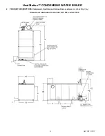
Page 6: ...HeatStation CONDENSING WATER BOILER 6 34 1161 05 17 2 PRODUCT DESCRIPTIONS Component Controls and Connection Locations Locations May Vary Dimensional information for HS 1000 HS 1250 and HS 1500...

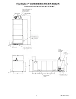
Page 7: ...HeatStation CONDENSING WATER BOILER 7 34 1161 05 17 Dimensional information for HS 1750 and HS 2000...

Page 8: ...f the National Electrical Code ANSI NFPA No 70 In Canada the electrical service must conform to local electrical codes and or CSA C22 1 Canadian Electrical Code Part 1 All wiring between the unit and...

Page 9: ...odes or regulations that may apply are the National Electric Code State Regional National drain water and flue emissions regulations the National Fuel Gas Code Building Construction and Safety Codes t...

Page 10: ...LER 10 34 1161 05 17 IMPORTANT Do not use the plumbing connected to the appliance as a ground for welding or any other purpose Example of a Single Boiler Primary Only Installation Example of a Multi B...

Page 11: ...HeatStation CONDENSING WATER BOILER 11 34 1161 05 17 Example of a Single Boiler Primary Secondary Only Installation Example of a Multi Boiler Primary Secondary Only Installation...

Page 12: ...or the return sensor located in the lower for operation as needed As the HeatStation is shipped the controlling sensor is the supply sensor If return sensor control is preferred refer to Section 10 fo...

Page 13: ...trap assembly from the union downward and rotate the outlet vertically to maintain a three 3 inch distance from the hose connector to the floor IMPORTANT Do not rotate the trap U bend toward the ceil...

Page 14: ...ere the 3 threaded end cap can be removed to recharge the Neutralizer with crushed limestone a The CNS must be located such that condensate will flow downhill from the condensate trap outlet to the in...

Page 15: ...njury or death 6 3 Inlet Pressure Measure at the inlet pressure tap located at the main gas cock The inlet pressure must remain within the minimum and maximum values while the unit is at rest and whil...

Page 16: ...y piping connected to the appliance to isolate the burner and gas train from main supply gas in compliance with NFPA 54 National Fuel Gas Code and most local Codes 6 The gas system installer must clea...

Page 17: ...losure if communicating with the outdoors through horizontal ducts All Air From Inside The Building Follow the requirements of NFPA 54 National Fuel Gas Code ANSI Z223 1 section Indoor Combustion Air...

Page 18: ...rminal Duct Pipe 6 Duct 8 Duct 90 Elbow 20 feet 10 feet 90 Long Radius Elbow 12 feet 6 feet 45 Elbow 12 feet 6 feet The following remote air duct information is provided for use in design calculations...

Page 19: ...t combine remote air ducting of multiple appliances into a single remote air duct unless the combined remote air ducting system has been evaluated and designed by a specified duct design firm and the...

Page 20: ...n result in property damage personal injury or death 8 1 Vent Material Selection The HeatStation can safely use plastic venting in systems that use colder building return water throughout the year Hig...

Page 21: ...Length in Equivalent Feet Vent Size 6 All Models 8 Vent All Models 10 Vent All Models Max Equivalent Length 230 eq feet 340 eq feet 460 eq feet Vent pipe fittings reduce the maximum allowable vent le...

Page 22: ...rner of an L shaped structure 9 A vertical vent must exhaust outside the building at least 3 feet 0 91m above the point of the exit and at least 2 feet 0 61 m above the highest point of the roof withi...

Page 23: ...r tight seal 6 Clean and deburr all solid PVC pipe ends then trial assemble the entire vent system vent before joining with cement Mark the pipe and fittings to identify their locations then disassemb...

Page 24: ...lled it must be checked to confirm all joints in the vent system are air and water tight After the vent is assembled close the end of the vent with a taped plastic bag or some other temporary closure...

Page 25: ...ed to prevent it from lifting out of the drain under discharge pressure and must be routed to allow complete drainage of the valve and piping Do not plug the relief valve s or install a reducing coupl...

Page 26: ...ustable through a Touch Screen User Interface located in the front control panel The control is factory pre set at approximately 140 F Boiler Control Panel Section 10 1 in this manual for more informa...

Page 27: ...an RJ485 patch cable All communication between the PIM and control display as well as the power to the control display is through this cable Platform Ignition Module PIM ID Card Flame current test pi...

Page 28: ...system IGN The Hot Surface Igniter is hot and the gas valve has opened to attempt burner ignition 4 seconds BURN The Burner has ignited and the flame has been sensed WWSD The boiler is currently in Wa...

Page 29: ...the Target Temperature that it is currently trying to maintain at the control temperature sensor CNTL TEMP If there is no current requirement for heat the Target Temperature is displayed as SUPPLY Di...

Page 30: ...or the outdoor temperature and automatically adjust the Target setpoint up and down in order to provide the optimum system temperature based on changes in the outdoor temperature See Section 10 13 for...

Page 31: ...It is recommended that Isolation valves should be configured for normally open power close operation 10 8 Selecting the Supply or Return Sensor for Single Boiler Primary Only Control A four switch Di...

Page 32: ...by first turning on the HEAT SCHD using the arrow buttons 2 There are four setback schedule types 24hr 5 2 5 11 and 7DAY The 24hr schedule is a daily schedule that will follow the same program every...

Page 33: ...trol of boiler operation is complete always return this parameter to the AUTO setting 2 The second setting is OFF This setting will stop all control function and prevent the burner from operating 3 Th...

Page 34: ...ture during the coldest weather can reduce up front system costs as well as improve the space heating comfort level When Outdoor Reset operation is desired there are additional control settings that n...

Page 35: ...to the PIM control terminal as illustrated below Connect Outdoor Sensor to the ORD and GND terminals Use 18 AWG or similar wire between control and sensor Do not run the wires parallel to telephone or...

Page 36: ...e MOD COM parameter set at 75 when the Master boiler reaches 75 burner modulation rate the EOS will enable boiler 2 and reduce the modulation rate to a minimum As the heat load increases the EOS will...

Page 37: ...but the correct state should be verified during setup MOD COND 50 to 100 For Parallel modulation this parameter will select the burner modulation percentage once reached will trigger the next boiler...

Page 38: ...the call for heat will be made and the burner will operate at the firing rate defined by the MIN MOD setting located in the SOURCE MENU 10 When the signal reaches 10 0Vdc the burner will operate at t...

Page 39: ...ystem 10 18 Using Tool Box Menu The TOOL BOX MENU contains several adjustable parameters as well as up to the 15 past alarm messages logged 1 The first screen in the Tool Box is for the ACCESS level T...

Page 40: ...ugh the gas valve If no mechanical cause can be found replace flame control 2 19 FLAME FAIL Flame failure indicates that during the burner ignition process the burner either failed to light or it did...

Page 41: ...fter ignition failure In this case the lockout may only be reset by the on board manual reset button or the remote reset input 11 8 ID Card Boil OUT Indicates a problem with the supply temperature sen...

Page 42: ...System L1 L2 Used for incoming 120VAC power supply connection Terminal L1 is the hot terminal Black and L2 is neutral White See the product catalog or specification document for circuit ampacity rati...

Page 43: ...ULATOR output on the component terminal strip provides a 120 Vac 0 5 amp pilot voltage to control a boiler water isolation valve Do not directly energize the valve actuator through these terminals The...

Page 44: ...mbined in a common probe body with the supply sensor located in the upper header The PIM compares the high limit temperature with the supply sensor temperature If the two temperatures are not the same...

Page 45: ...emperature of the controlling sensor is compared to the temperature control set point to determine when to begin firing in heating mode d The boiler remains in heating mode and with extended operation...

Page 46: ...upply in accordance with the Nameplate Rating Adequate uncontaminated indoor or outdoor combustion air Adequate Fuel Supply Adequate Boiler Water Supply 30 gpm min flow Exhaust Vent that complies with...

Page 47: ...he available gas type is not correct contact Rverside Hydronics for instructions CONFIRM THE SUPPLY GAS PRESSURE WARNING If you smell gas Do not try to light any appliance Do not try to touch any elec...

Page 48: ...t Proving failure message 3 Now open the manual shutoff gas valve at the burner Then push and release the MAIN RESET button on the front panel of the boiler to recover from the lockout condition If al...

Page 49: ...rner is firing the burner will shut down and recycle i Using the UP or DOWN arrow buttons adjust the firing rate from OFF to the minimum firing rate of 10 for Low Fire j If the CO2 levels at Low Fire...

Page 50: ...ME button for 3 seconds to display the SETUP Menu 2 Using the NEXT ITEM or ITEM BACK buttons navigate to the TOOLBOX menu then touch the ENTER button to display the ACCESS menu 3 Now press and hold th...

Page 51: ...or erratic ground Follow the Initial Startup instructions in Section 14 as the first step in any troubleshooting Verify that the system is powered and that the thermostat is calling for heat If the c...

Page 52: ...f blocked flue switch Check for voltage at the common side of blocked switch Check if switch tubing is connected on both ends Flow switch Indicated by Remote Equipment Proving failure message Verify p...

Page 53: ...r rating Low Voltage Fault 5 flashes Check the 24 VAC input voltage The voltage must be above 18 0 VAC Vent Temperature Fault 6 flashes Check for a blocked flue Check the vent sensor and connections H...

Page 54: ...X 310 MM 126852 126852 3 BURNER WORGAS 140 X 648 MM 125559 125559 125559 4 INTAKE AIR DUNGS WHIRLWIND 126864 126864 126864 4 INTAKE AIR DUNGS WHIRLWIND 126895 126895 5 ADAPTER FLEXIBLE RUBBER 6 X 5 12...

Page 55: ...EED 122346 122346 122346 122346 122346 11 SWITCH AIR PROVING CLEVELAND CONTROLS 111208 111208 111208 111208 111208 12 FLAME CONTROL PIM FENWAL 143623 143623 143623 143623 143623 13 TRANSFORMER STEP DO...

Page 56: ...K 1 1 2 X 7 57612 57612 7 NIPPLE BLACK 1 1 2 X 4 6057 6057 8 NIPPLE BLACK 1 X 2 6011 6011 6011 6011 6011 9 ELL BLACK 90DEG 6163 6163 6163 47330 47330 10 ELL BLACK 90DEG 6163 6163 6163 44699 44699 11 S...

Page 57: ...HeatStation CONDENSING WATER BOILER 57 34 1161 05 17 16 4 Component Wiring Details...

Page 58: ...or excessive gas A blocked heat exchanger can cause unsafe operation and will reduce efficiency To inspect and clean the heat exchanger a qualified service agent or installer should use the procedures...

Page 59: ...sure the flow of combustion and ventilation air is unobstructed to the appliance 9 When electrical controls are serviced or replaced label all connections as they are removed to know the proper place...

Page 60: ...7 Inspect burner and gas train components for wear or deterioration 8 Check the electronic ignition system for quick ignition and proper flame signal 9 Check gas safety shut off valves for proper oper...

Page 61: ...HeatStation CONDENSING WATER BOILER 61 34 1161 05 17...

Page 62: ...ter conditions or maintenance the warranty on the heat exchanger does not cover poor performance structural failure or leaking due to an excessive accumulation of scale MODEL NUMBER SERIAL NUMBER INST...

Reviews: