HeatStation™ CONDENSING WATER BOILER
38
34-1161 05/17
10.16 EMS Control (Energy Management System)
The EMS function will allow the user to directly control either the Target temperature or Direct Drive of the
boiler/burner through the use of an external analog signal. This function can be configured to respond to 0-10, 2-10
Vdc or 4-20 mA. Utilize DIP switches 2, 5, 6.
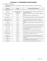
Enabling this function requires adjustments to both the PIM(Platform Ignition Module) and the BTCII(HMI). See the
following Section on PIM DIP Switch Options for details on PIM settings. The parameters in the table below are
located on the BTCII.
Parameter
Range
Description
APP
RESET, SETP,
EMS,DDHW, POOL
The default application mode is SETP, to enable energy
management system control using an analog signal, change this
parameter setting to EMS. DIP switch #5 must be on for EMS
menu to be present.
SIGNAL
0-10Vdc, 2-10Vdc
When DIP switch #6 selects 0-10Vdc this parameter can also
allow for a truncated signal of 2-10Vdc.
SETP LO
Boil MIN to SETP HI
This setting will define the EMS Target when The EMS signal =
1.0Vdc(0-10Vdc) or 2.0Vdc when (2-10Vdc) is selected.
SETP HI
SETP LO to Boil
MAX
Defines the EMS Target when the EMS signal = 10.0 Vdc
If the EMS control method is Target temperature, consider the following example:
Example: 0-10Vdc is selected. The SETP LO is set to 100° and SETP HI is set to 180°F. When the 0-10Vdc signal
rises from 0 to 1.0Vdc, the call for heat will be made and the Target temperature will be set at 100°F. When the
signal reaches 10.0Vdc, the Target temperature will be 180°F. The Target temperature will vary linearly between 1-
10Vdc.
If the EMS control method is Direct Drive of the boiler/burner, consider the following example:
Example: 2-10Vdc is selected. When the 2-10Vdc signal rises from 0 to 2.0Vdc, the call for heat will be made and
the burner will operate at the firing rate defined by the MIN MOD setting located in the SOURCE MENU (~10%).
When the signal reaches 10.0Vdc, the burner will operate at the firing rate defined by the MAX MOD setting located
in the SOURCE MENU (~100). The burner will modulate linearly between 1-10Vdc.
Do not attempt to adjust the
MIN MOD or MAX MOD setting. Unsafe operation can occur.
When 4-20mA i
s applied, a 500Ω, 1/2W resistor is placed across the EMS terminals. The method of operation and
adjustment are the same. At a 4mA signal, the PIM will see a 2VDC signal, at 20mA signal, the PIM will see a 10VDC
signal.
10.17 PIM DIP Switch Selectable Options
There is an 8 DIP switch panel on the front of the PIM. Some options must be enabled by turning on the applicable
DIP switch. All DIP switches are in the OFF position as supplied.
1. Switch #1
– The EOS uses a PID algorithm to regulate system temperature. The
OFF position (default) of this switch selects Auto Differential. This allow the BTCII
to regulate system temperature with optimum accuracy. The on position will in turn
select Manual Differential. This state should only be selected when advised by the
Riverside Hydronics application specialist.
2. Switch #2
– This switch selects the type of EMS control. The OFF position (default)
will adjust Target Temperature when EMS is enabled. The ON position will allow
for Direct Drive of the boiler/burner. See the EMS Section for more details.
Switch #3
– This switch selects control logic used for isolation valves or boiler
pumps. When using an Isolation valve in a Primary only system, switch #3 should
be left in the OFF position. In the OFF position the EOS will power the
CIRCULATOR circuit when the heating cycle is over in order to close the valve.
For a Primary/Secondary system, switch #3 should be in the ON position in order
to power this circuit for operation of a pump during boiler operation.
ON = Sends signal to run a pump.
OFF = Sends signal to close isolation valve.

