HeatStation™ CONDENSING WATER BOILER
41
34-1161 05/17
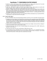
11.3 Replacing the Fuse
The 24 VAC input and output circuits of the PIM are protected by a 8.0 Amp fuse.
11.4 Self-Check / Control Failure
The PIM confirms the integrity of the gas valve relay contacts to insure safety. It also monitors the processor memory
and software execution for proper program flow. If the control detects an error in its software or hardware, all outputs
are turned off and the LED displays a steady ON condition. If this condition persists after an attempt to restart then
the control must be replaced.
11.5 System Safety Checks
The PIM monitors the safety switches, temperature sensors, supply voltage, and blower speed and will go to soft
lockout until the error condition is corrected. Individual LED diagnostic codes or messages on the RS485
communications help identify the problem for efficient troubleshooting.
11.6 Flame Current Measurements
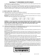
The PIM supports direct measurement of flame signal strength using the flame current test pins (FC+, FC-) on
connector P2. Flame current may be measured by a micro-ammeter, or alternately by using a standard digital
voltmeter. The signal on P2 is calibrated to 1 micro-amp/volt, so flame current in micro-amps can be directly read on
the volts scale.
The control display user interface is capable of displaying an approximation of flame current up to 5 micro-amps
.
11.7 Non-Volatile Lockout / Manual Reset
The PIM normally allows for volatile ignition lockout where a lockout condition is reset by a loss in 24VAC power or
the call for heat demand. In certain applications or where required by standards (such a CSD-1), it can be configured
through the parameter settings for non-volatile lockout after ignition failure. In this case the lockout may only be reset
by the on-board manual reset button, or the remote reset input.
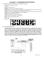
11.8 ID Card
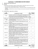
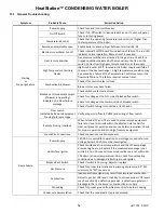
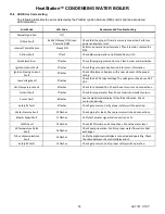
Boil OUT
Indicates a problem with the supply temperature sensor, possibly a
broken or shorted sensor wire or failed sensor.
NOTE:
The boiler supply
sensor and the high limit sensor or located in the same probe body.
8
11
HI LIMIT
Indicates a problem with the high limit temperature sensor, possibly a
broken or shorted sensor wire or failed sensor.
NOTE:
The boiler supply
sensor and the high limit sensor or located in the same probe body.
8
14
Boil INLET
Indicates a problem with the boiler return temperature sensor, possibly a
broken or shorted sensor wire or failed sensor.
8
12
VENT
Indicates a problem with the vent temperature sensor, possibly a broken
or shorted sensor wire or failed sensor.
8
13
LOGASPRES
FAIL
The low gas pressure safety switch is not sensing the minimum gas
pressure required for safe burner operation. Check the gas pressure to
ensure that the minimum is available. If the gas pressure is adequate
check for fluctuating gas pressure or a faulty pressure switch.
9
10
REM PROV FAIL
The remote proving circuit checks for proper operation of the water flow
switch, as well as ancillary mechanical room equipment. Verify minimum
water flow as well as proper wiring and function and flow switch and
ancillary mechanical equipment. See Sec 12.2.
10
8
LOW WATER
FAIL
The electronic low water cutoff is no longer sensing water at its probe.
This could also be caused by a faulty low water board or sensor
12
7
HTR LOST
This could be caused by a poor connection between the PIM control and
the digital control display or failure of either device.
14
6
HIGASPRES
Check the gas pressure to ensure that the building supply doesn’t exceed
the value on the boiler rating plate. If the gas pressure is within rated limit,
check for a faulty pressure switch.
15
26

