HeatStation™ CONDENSING WATER BOILER
52
34-1161 05/17
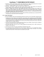
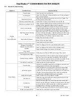
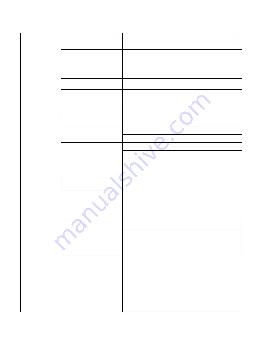
15.1 General Troubleshooting
Symptom
Probable Cause
Corrective Action
Starting
or
Pre-purge Failure
Power Supply
Check fuse and/or circuit breaker.
On-Off Switch
Check if On-Off switch is illuminated when on. If not check panel
fuse or incoming power.
Temperature Control
Check that the operating temperature control is set higher than
the temperature of the boiler.
Remote enable/disable open
Enable boiler or place jumper between terminals R1-R2.
Electronic Low Water Cut-off
Check internal ELWCO board for indication of failure. The red LED
indicates normal operation. Manual reset is required.
Gas Pressure Switches
Gas pressure switches are attached to the gas train. Check for a
tripped condition indicated by the manual reset button on the
switch. Correct low/high gas pressure condition at the supply.
High Temperature Limiting
Device
High limit is set at 210°F, located in the boiler supply manifold at
the top of the heat exchanger. A high temperature condition may
be caused by a failure of the Temperature Control sensors or the
flow switch failure. This failure requires manual reset.
Combustion Air blower
Check if fan control relay is closed.
Blower motor may have failed.
Blocked vent/condensate switch
(if blower is operating)
Indicate by Air Flow Failure
message
Check switch contacts are closed.
Check for voltage at the N.O. side of blocked flue switch.
Check for voltage at the common side of blocked switch.
Check if switch tubing is connected on both ends.
Flow switch
Indicated by Remote Equipment
Proving failure message
Verify proper min flow (30 GPM) and wiring of flow switch.
Remote Proving Interlock
When terminal C1 and C2 are used to prove remote equipment,
failure to close this circuit within the allotted time for Call-for-
Heat will prevent operation and cause an alarm indication. Check
for proper operation and proving of remote equipment.
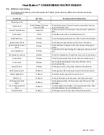
Loose Wire Connections
Check connections to all components.
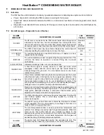
Flame Failure
Power Supply
120 VAC is required for operation. Low voltage can cause failure.
Voltage below 110 VAC must be investigated.
Hot Surface Igniter
Check resistance at room temperature and then the amperage
draw during heat-up. Replace if the measured amperage is not
within 3.5 to 5.0 Amps or if measured resistance is not within 40-
100 ohms (at room temperature). Also, check for overheating
condition due to damaged refractory around igniter.
Blocked Vent Switch
Check if switch is bouncing. Adjust or replace.
Gas Pressure
Check for proper inlet static and dynamic gas pressure, 3.5" WC
minimum, 14" WC maximum.
Combustion
Inadequate flame signal may result from improper combustion.
Adjust to proper CO2 levels. Inability to achieve proper CO2 levels
may be caused by a defective gas valve, a defective regulator or
blockage in the in the burner or combustion air supply.
Grounding
Check for proper ground from flame control to burner housing.
Condensate Accumulation
Check that the condensate trap is not blocked.


