background image


Page 1/ 24 


34-81  10/2013 

SERVICE & SETUP MANUAL 


BOILER 

ELECTRONIC CONTROLLER 


Riverside Hydronics, LLC  •  3220 Galvez Ave  •  Fort Worth, Texas 76111  •  800-990-5918


Summary of Contents for TempTrac

Page 1: ...Page 1 24 34 81 10 2013 SERVICE SETUP MANUAL BOILER ELECTRONIC CONTROLLER Riverside Hydronics LLC 3220 Galvez Ave Fort Worth Texas 76111 800 990 5918 ...

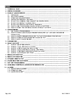
Page 2: ...ETER VALUES IN Pr2 ______________________________ 9 4 5 HOW TO LOCK THE KEYBOARD _________________________________________________ 9 5 PARAMETERS ___________________________________________________________________ 10 6 RELAY OUTPUTS ________________________________________________________________ 14 6 1 OUTPUT SETUP AND SPECS __________________________________________________ 14 6 2 OUTPUT 1 CALL ...

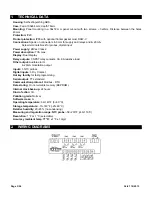
Page 3: ...ay Dual display Relay outputs 3 SPST relay contacts 3A 8A resistive load Other output Audible alarm 4 20mA modulation output Inputs 3 NTC probes Digital inputs 3 Dry Contact Hot key facility for fast programming Serial output TTL standard Communication protocol Modbus RTU Data storing On non volatile memory EEPROM Internal clock back up 24 hours Kind of action 1B Pollution grade Normal Software cl...

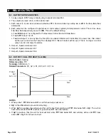
Page 4: ...orking hours of the load relays In programming mode it browses the parameter codes or decreases the displayed value CLOCK Changes lower display from inlet temperature to current time and day To set the current time and day EXT Changes upper display between outlet temperature inlet temperature outdoor reset temperature modulation or the temperature difference between the inlet and outlet temperatur...

Page 5: ...dS1 or dS2 is set to display the modulation output value ANI Flashing Modulation is forced to value in i1S by digital input 1 ON Modulation output signal is automatically controlled by temperature probe 1 Flashing Modulation output time delay is activated Modulation output will remain at 4mA until the AC4 time delay expires Or Modulation will remain in low fire until probe 2 is below TH4 by the am...

Page 6: ... display information described above is available for monitoring through the optional MODBUS RTU interface 3 4 LOWER LED READOUT YELLOW The default display of this readout is the temperature sensed at Probe 1 which is generally inserted into the return inlet piping of the boiler Probe 1 may display the tank stored water temperature supplied outlet water temperature flue gas temperature ambient tem...

Page 7: ...for automatic operation 3 To adjust modulation manually push the key the value starts flashing Then use or keys to modified it 4 To exit press and or wait 30s without pressing any key NOTE After a modification it will be possible to enter the Modulation output setting without entering the password for 10min After this time you will be asked for the password again 3 8 HOW TO SEE THE WORKING HOURS O...

Page 8: ...OT PASSWORD PROTECTED 1 Enter the Programming mode by pressing the and key for 3s 2 Select the required parameter The name of the parameter is on the upper display and its value is on the lower display 3 Press the key the value of the parameter will start blinking 4 Use or to change the value 5 Press to store the new value and move to the following parameter To exit Press and and or wait 30s witho...

Page 9: ...it Press and or wait 30s without pressing a key NOTE the new programming is stored even if the procedure exits by time out 4 5 HOW TO LOCK THE KEYBOARD 1 Keep the and keys pressed together for more than 3 s 2 The PoF message will be displayed and the keyboard is locked At this point it is only possible to view the set point Any attempt to change a set point will display the PoF message 3 Repeat st...

Page 10: ...x30E 783 LS3 0 3 0 5 Minimum set point 3 St3 40 F St3 Pr2 Pr2 0x30F 784 uS3 0 3 0 5 Maximum set point 3 St3 St3 230 F Pr2 Pr2 0x310 785 AC3 0 3 0 5 Anti short cycle delay for output 3 0 30 min Pr2 Pr2 0x311 786 o3P 0 3 0 5 Probe selection for output 3 Pb1 Pb2 Pr2 Pr2 0x312 787 SSE 0 3 0 5 Set point shift for output 3 enable disable No Yes Pr2 Pr2 0x313 788 HY5 0 3 0 5 Differential for set point 5 ...

Page 11: ...erature alarm recovery 1 45 F Pr2 Pr2 0x330 817 ALd 0 3 0 5 Temperature alarm delay 0 255 min Pr2 Pr2 0x331 818 dAo 0 3 0 5 Delay of temperature alarm at start up 1 10 min disp 0 1 0 23h 50 min Pr2 Pr2 0x332 819 ANALOGUE INPUTS oF1 0 3 0 5 First probe calibration 21 21 F Pr3 Pr2 0x333 820 P2P 0 3 0 5 Second probe presence No Yes Pr2 Pr2 0x334 821 oF2 0 3 0 5 Second probe calibration 21 21 F Pr3 Pr...

Page 12: ...put 2 is always on or depending on temperature rEG 1 1 YES 0 1 no 0 0 Pr2 Pr2 0x357 856 3on 0 3 0 5 The output 3 is always on or depending on temperature rEG 1 1 YES 0 1 no 0 0 Pr2 Pr2 0x358 857 OTHER Adr 0 3 0 5 Serial address 0 247 Pr2 Pr2 0x359 858 Ptb 0 3 0 5 Parameter map code always 1 readable only Pr2 Pr2 0x35A 859 rEL 0 3 0 5 Software release 5 0 5 3 0 3 readable only Pr2 Pr2 0x35B 860 i1S...

Page 13: ...goes away or need for call for heat goes away bit 10 or 11th bit Pr2 0xD00 3329 0 5 ALARM 2 Lockout stops heating Input 2 Flash AL2 Lguage valve 2048 or 0x1000 bit 11 or 12th bit Pr2 0xD00 3329 0 5 ALARM 3 Lockout stops heating Input 3 ALMMB ALOAF beep Flash AL3 Hguage valve This is ALARM ON ANY FAILURE 4096 or 0x0800 bit 12 or 13th bit Pr2 0xD00 3329 0 5 Maintenance Relay1 beep Flash Nn1 wrench 8...

Page 14: ...contact will be open and when the TempTrac displays OFF this will contact will be open This is no longer a control output and is not subject to alarms 5 Output 1 Spade terminals 4 5 6 Output 2 Spade terminals 6 7 7 Output 3 Spade terminals 8 9 6 2 OUTPUT 1 CALL FOR HEAT 1on rEG Kind of action Heating Reference probe TP1 Terminals SPADE 4 5 Related Parameters St1 Hy1 LS1 US1 AC1 i3F 1on time time O...

Page 15: ... output temperature control when oS2 Std otherwise output 2 is an alarm output contact 2 S2c determines if St2 is relative to St1 or independent S2c dep or ind 3 Hy2 functionality same as Hy1 See OUTPUT 1 CALL FOR HEAT 6 4 OUTPUT 2 AS ALARM RELAY oS2 AL 2ON REG 1 Output 2 will function as an alarm contact when oS2 AL 2 When an alarm condition occurs Output 2 will be energized relay closes as an in...

Page 16: ...ction Heating Reference probe TP1 or TP2 Terminals SPADE 8 9 Related Parameters S3c St3 Hy3 LS3 uS3 AC3 3on o3P time time Out3 Probe2 Set3 Set3 Hy3 NOTES 1 Output 3 can be used to enable pumps when temperature falls below a St3 2 o3P will select the probe for Output 3 Pb1 or Pb2 ...

Page 17: ...rgized state off Output 3 will function according to St3 When Output 1 is in an energized state Output 3 will function according to St5 2 ACA delays the change from St3 to St5 3 o3P selects temperature probe to be referenced by Output 3 4 Hy1 Hy3 and Hy5 are active but not shown in this illustration Set Point Shift Set 3 Set 1 Set 5 On Out 3 Off On Out 1 Off Time Set 3 Set 5 Set 3 Alternate Set Po...

Page 18: ...dently from the value of the probe and the value of the PS4 parameters After digital input 1 is no longer ACTIVE the analog output will stay at the actual mA value set in i1S for the time period set by at the i1t parameter 4 If the probe TP1 is broken PS4 nu and the digital input 1 is off the value of the modulation output depends on the PP4 parameter 5 The value of the PS4 parameter can be set di...

Page 19: ...ature is lower than tt the dynamic reset of the St1 action starts as described in the following diagrams Temper Outdoor Temper Set1 rr1 Set1 tt rr2 tt NOTES 1 With rr1 0 the dynamic reset of the set point 1 is disabled 2 If the TP3 is not present P3P no or broken the dynamic reset of the set point 1 is disabled 10 WARM WEATHER SHUT DOWN The tt2 parameter referring to the outdoor probe TP3 establis...

Page 20: ...ck of the control Press and keys together momentarily then press the key The uPL message will appear while uploading is occurring and the End message will appear when finished Push any key to return to normal operation ON OFF Press the ON OFF key to turn off the control Insert the HOT KEY into the TTL connection on the back of the control Press the ON OFF key again and downloading will begin The D...

Page 21: ... zero is displayed 5 Use UP or DOWN keys to input the Passkey in the flashing digit confirm the figure by pressing SET The Passkey is 321 6 Once you have entered the Pr2 menu press the DOWN key until the parameter Adr appears on the screen as shown to the right 7 Now press the SET key once and the number will begin to blink Use the arrow key to set the address Each TempTrac on a RS 485 network mus...

Page 22: ...nput 1 signal alarm is still active until a button is pressed See i1F i1P i1d AL2 Digital Input 2 is ACTIVE for one or more of the conditions listed in section Audible Alarm Audible alarm sounds There is a time delay before this alarm is ACTIVE Opens all temperature controlled outputs Lockout condition See oS2 i2d i2P i2F AL3 Digital Input 3 is ACTIVE for one or more of the conditions listed in se...

Page 23: ...ed only if Output 1 is energized 3 When digital input 2 is ACTIVE AL2 will flash Digital Input 3 Screw terminal 20 COM 21 1 When a signal is continuously present for number of minutes in parameter i3d the input is then ACTIVE 2 When i3F No Digital input 3 ACTIVE functions as an alarm independent of output 1 AL3 will flash for this condition 3 When i3F Yes Digital input 3 ACTIVE functions as an ala...

Page 24: ... input 1 alarm recovers automatically when the need for output 1 stops Manual recovery is required when the condition of Input 1 is removed but the need for output 1 is still present Pressing any button will reset this condition 4 The digital input 2 3 alarms recover when condition s listed above are normalized and any button is pressed 5 RTC alarm stops after programming the real time clock 6 RTF...

Reviews: