Page 18/ 24
34-81 10/2013
7. MODULATION
OUTPUT
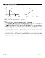
Kind of action
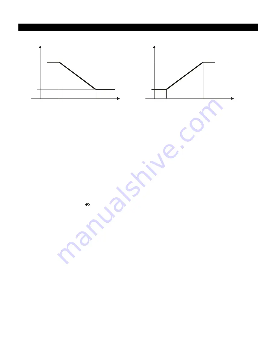
: if Sr< 0 Heating; if Sr>0 Cooling. See diagrams.
Current
(mA)
Temper.
20
4
Set4 + Sr
Set4
Sr < 0
Current
(mA)
Temper.
20
4
Set4
Set4 + Sr
Sr > 0
Reference probe
: TP1
Related Parameters:
S4c, St4, Sr, PS4, PP4, Ac4, i1S, i1t, i1F, i1d
NOTES
1. The kind of action of the modulation output depends on the sign of the
Sr
parameter.
2. If the parameter
PS4
is different from
nu
, the percentage of the modulation output depends on the value set in
PS4
, independently from the value of the probe. (0-100% represents 4mA to 20mA.)
3. If
i1F=No
and digital input 1 is ACTIVE, the analog modulation output is forced to the mA set in
i1S
parameter
independently from the value of the probe and the value of the
PS4
parameters. After digital input 1 is no longer
ACTIVE, the analog output will stay at the actual mA value set in
i1S
for the time period set by at the
i1t
parameter.
4. If the probe
TP1
is broken
, PS4=nu
and the digital input 1 is off, the value of the modulation output depends on
the
PP4
parameter.
5. The value of the
PS4
parameter can be set directly by the keyboard. See par. 3.6.
6. Anti-short cycle delay for the analog output: when the analog output reaches the 4mA, it is held at 4mA for this
time. During this time the
icon is flashing. When this delay has expired, normal functioning of modulation
output restarts. This delay will be reinitiated again after output 1 switches off.
7. Ranges:
i1S
(4-20 range) is actual mA,
i1t
(0-30 range) is seconds.
PS4
&
PP4
(0-100 & nu range) is percentage
of output 0%=4mA 100%=20mA nu=AUTO.


