Page 23/ 24
34-81 10/2013
13.1 DIGITAL INPUT ALARMS
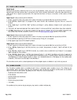
Digital Inputs
Polarity of the inputs is determined by the i1p, i2p, i3p parameters. If they are set to “CL” (closed) then a signal is
present when the input terminal has a connection to the common (COM) terminal #21. When the parameter is set to
“OP” (open) then a signal is present when the input terminal does not have a connection to the common (COM)
terminal.
Digital Input 1
(Screw terminal #18, COM #21)
1. When a signal is continuously present for number of minutes in parameter
i1d,
the input is then ACTIVE.
2. When
i1F=Yes
, Digital input 1 is assigned to the alarm function and considered only when there is a need for
Output 1.
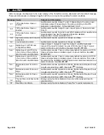
3. When digital input 1 is ACTIVE, “
AL1”
will flash, and Output 1 will be disabled. Output 2 and 3 will continue to
function.
4. This alarm will reset automatically if the need for Output 1 is removed (Probe 1 temperature rises above setpoint).
5. If
i1F=No
Digital Input 1 is not used as an alarm, but used as way method of forcing a specified modulation rate.
See details about the
i1S
modulation function; refer to the
MODULATION Output
section of the manual.
Digital Input 2
(Screw terminal #19, COM #21)
1. When a signal is continuously present for number of minutes in parameter
i2d,
the input is then ACTIVE.
2. When
i2F=Yes
, Digital input 2 ACTIVE is considered only if Output 1 is energized.
3. When digital input 2 is ACTIVE, “
AL2”
will flash.
Digital Input 3
(Screw terminal #20, COM #21)
1. When a signal is continuously present for number of minutes in parameter
i3d,
the input is then ACTIVE.
2. When
i3F=No
, Digital input 3 ACTIVE functions as an alarm independent of output 1. “
AL3
” will flash for this
condition.
3. When
i3F
=
Yes
, Digital input 3 ACTIVE functions as an alarm and is considered only if Output 1 is energized.
“
AL3
” will flash for this condition.
4. When
i3F=Edi
, Digital input 3 ACTIVE de-energizes Output 1, and alarm conditions will not be registered in
memory or indicated in any way until Digital input 3 deactivates. Note: no existing alarm indication will be shown
until Digital input 3 state changes (neither an alarm icon, the
AL#
indication on the display nor the audible alarm
activation). (This feature is still subject to the
i3d
timer.)
The Instrument will revert to normal operation when these digital inputs are di any button is pressed.
13.2 AUDIBLE ALARM
The TempTrac audible alarm is activated each time a connected alarm condition occurs. The following are
representative alarm conditions that may be connected to and activate the TempTrac audible alarm (some alarms
may be connected to and operate separately from the TempTrac on some products).
-
High/low water temperature alarm
-
Probe
failures
-
External thermostat limit failure
-
Flame
Failure
-
High and low gas pressure
-
Low
water
The audible alarm is silenced by pressing any key (alarm condition still present).


