background image

Aluminum Base Angle

Aluminum Base
Angle

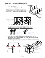
1. Identify the 2''x 3'' Aluminum Base Angle (ABA).

2. Place ABA against the side groundrails (3'' down 2'' up)

2"

3"

3. Slide the ABA past the end of the groundrail 3''. Mark on

the 2'' side of the angle where the groundrail ends and cut

2'' side on the line.  The 2'' side of the ABA will be flush

with the groundrail, and the 3'' side will hang past the

groundrail 3''.

base angle
profile

2''

3''

cut line

3"

over hang

3"

4.

After  notching  the  initial  piece  of  ABA,  continue  placing  angle  end  to  end  down  the  side

groundrail.  Repeat  notching  process  at  opposite  end  of  greenhouse.   

*Remember*    when

cutting ABA at opposite end of greenhouse, DO NOT cut the ABA flush with groundrail.
Cut 3'' longer than groundrail and notch the 2'' side back 3'' see detail A
.

5. Lay ABA across the front & rear of the greenhouse.  Place a piece of ABA against the 3'' over

hang at the corner of greenhouse.  Make sure that the ABA is held against the front groundrail,

mark  the  ABA  at  the  door  stud  and  cut  off  flush  with  the  inside  edge  of  door  stud 

see  5a

.

Repeat for opposite side of door and rear of greenhouse.  

If you do not have a door in the rear

of greenhouse, lay ABA end to end to equal the width of the greenhouse.

over hang

3"

detail A.

3.

4.

5.

5a.

ABA

angle

end to end

rear groundrail

corner leg

ABA

corner leg

front groundrail

ABA

side groundrail

side groundrail

side groundrail

red = ABA cut flush with door stud

door stud

endwall stud

corner leg

front groundrail

door opening

ABA flush against

3''overhand

Page 19

Summary of Contents for Thoreau Series

Page 1: ...m i u m E d u c a t i o n a l G r e e n h o u s e Assembly Manuals for Models 12 w x 18 d x 9 5 h 12 w x 24 d x 9 5 h Customer Service 877 373 3078 Email customerservice rsiww com 65 Fleetwood Drive Rockaway NJ 07866 ...

Page 2: ......
Page 3: ...with 4 ties evenly spaced gray dashed lines groundrails for greenhouse END VIEW OF TYPICAL CONCRETE SLAB When pouring concrete slab be sure to make the slab 10 longer and 8 wider than your order size An example is shown above OVERHEAD VIEW concrete slab shows a greenhouse order for a 12 x 24 Scholar The slab is poured 12 8 wide and 24 10 long Set front rear groundrails 4 inward from edge of concre...

Page 4: ... for groundrails and install them onto the inside of the groundrails at every welded stanchion and 3 to 4 from the corners on the side groundrails see below illustration welded stanchions GROUNDRAIL L BRACKETS SIDE GROUNDRAIL FRONT REAR GROUNDRAIL 3 4 14 tek screws stanchion for 2 x 2 Leg stanchion for 2 x 2 Leg GROUNDRAIL L BRACKET TOP OF GROUNDRAIL INSIDE OF GROUNDRAIL TOP OF GROUNDRAIL Page 2 ...

Page 5: ...nchion for leg Detail A 3 Connect the front rear groundrails to the side groundrails all L brackets should be facing toward the inside of your greenhouse see Detail A Make sure groundrails are square before securing to foundation 4 Secure connected groundrails to foundation see Detail B equal measurements side groundrails side groundrails DETAIL B 1 2 x 5 1 2 concrete anchor bolts Page 3 ...

Page 6: ...cking slip for specific quantities of each part 2 Attach L brackets to half bows as shown below for a 12 wide greenhouse Slide half bows onto center connector and secure with 14 x 1 tek screws 3 Attach U bolts to each L bracket using 1 4 nuts do not tighten at this stage Purlin Hanger L brackets MUST be facing the inside of the greenhouse on END BOWS Purlin Hanger L brackets on Intermediate bows c...

Page 7: ...ntermediate Bow to Column Brackets 4 Insert the brackets into the top of the legs let the 1 flat bar rest on the lip of the leg as shown below Note on the corner brackets the 1 flat bars have to be facing each other as indicated in corner bracket profiles 5 Take the assembled rafters and slide them onto the column brackets and secure working from the inside of the greenhouse using 14 tek screws as...

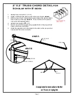
Page 8: ... the legs detail B Truss chords are to be placed only on the intermediate rafters 4 Identify truss uprights 13 8 x 47 5 Secure one end of the upright using supplied bolts to the pre punched holes on the truss chord 2x2 6 Attach the opposite end of the upright to the rafter at the pre punched hole nearest the center connector TRUSS CHORD 2 X 2 L BRACKET detail A detail B Completed Intermediate Raft...

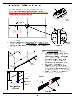
Page 9: ...roof purlin detail B PREPARING of ROOF PURLIN Identify 1 3 8 x 12 5 purlin with swedge 1 connect the appropriate number of purlin together to equal the length of your greenhouse see detail C You may have excess you will cut it off at a later time 2 Next lay the connected purlin on the ground flush with the end of the side groundrail see overhead view of corner 3 Make a mark 2 from the end this rep...

Page 10: ...r using the marks that you made on the purlin line up the back side of the rafter and tighten u bolt on to the purlin 6 Move to the next rafter using the marks on the purlin line up the rafter and tighten u bolt onto purlin 7 Repeat this process for the remaining runs of purlin Individually tightening u bolts as you go and keeping the 70 distance between each rafter 8 Cut off any excess roof purli...

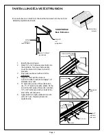
Page 11: ...ackets 3 Flush eave extrusion with end of the corner leg 4 Align the bolts with the holes in column to rafter brackets and apply 1 4 stainless steel nuts 5 To splice two pieces of Eave Extrusion use 2 x 6 aluminum splice plates At the end of the first piece of Eave Ext add two 1 4 x 3 4 bolts also add two bolts at the start of the second piece 6 Apply aluminum splice plate and secure with 1 4 nuts...

Page 12: ...reenhouse inside greenhouse 2 x 2 door stud welded stanchion groundraill tek screw thru door stud stanchion rafter endwall door stud horizontal purlin 2 x6 flat bracket 1 install front rear door studs over the welded stanchions and secure using 14 tek screws 2 view from inside and at the end rafter Connect the endwall studs to the rafters using 2x6 flat bracket and 14 tek screws 1 2 endwall horizo...

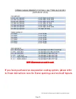
Page 13: ...tion manual with your endwall configuration Frame out measurements are provided for equipment fans shutters and doors that Atlas Manufacturing offer We recommend identifying your specific equipment sizes before starting the process of framing the endwalls Some endwall layouts will show framing out for Evaporative Cooling Systems This is for endwall framing only actual step by step instructions are...

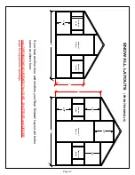
Page 14: ...n frame out for door frame out for fan frame out for fan frame out for door 2 7 1 2 2 8 2 8 3 3 5 8 If you have another door and shutters your Rear Endwall Layout will be the same as shown here see OPENING MEASUREMENT for FANS SHUTTERS and DOORS page for equipment openings Page 12 ...

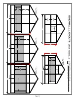
Page 15: ...2 10 10 3 10 10 4 10 8 8 12 12 12 3 x 10 Evaporative Cooling System 4 x 10 Evaporative Cooling System 5 x 10 Evaporative Cooling System 3 x 10 Evaporative Cooling System ALL FRAMING MATERIAL 2 x 2 SQUARE TUBING REFER TO OPENING MEASUREMENTS FOR FANS SHUTTERS AND DOORS PAGE FOR EQUIPMENT FRAME OUT SIZES 1 4 Page 13 ...

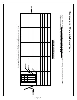
Page 16: ...ystem in the endwall you will need to mount the rear door in the sidewall of the greenhouse as seen below SIDE VIEW OF GREENHOUSE door header door stud horizontal purlin wall vent cooling system exhaust fan Refer back to Framing Endwalls page for door framing instructions Page 14 ...

Page 17: ...r 39 1 2 Square 45 Shutter 45 1 2 Square 48 Shutter 48 1 2 Square 60 Shutter 60 1 2 Square Door openings for 42 X 6 6 Swing door Set openings 42 1 2 Wide X 78 1 2 High 4 X 6 8 Swing Door Set openings 48 1 2 Wide X 80 High 36 X 6 8 Swing door Set openings 36 Wide X 80 High 6 X 6 8 French Door Set openings 72 Wide X 80 High 4 X 7 Single Sliding door Set openings 46 Wide X 82 High 8 X 7 Double slide ...

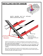
Page 18: ... not extend past the end rafter because it will damage the end wall covering when it is installed Bolt holes for the heater hanger brackets are to be field drilled into the rafters IMPORTANT insert the bolts from the outside of the greenhouse If inserted from the inside it damage end wall covering After you are comfortable with the placement of the heater hangers secure the heater hanger brackets ...

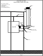
Page 19: ...PIECE ELBOW 4 PIECE 1 MIN ADAPTER PARTS GENERALLY REQUIRED 1 ADAPTER FOR DOUBLE WALL PIPE 2 WALL COLLARS 1 ADJUSTABLE ELBOW 1 VENT STACK LOT PCS DOUBLE WALL PIPE 10 METAL STRAPPING WALL BANDS HEATER HANGER DRILL WEEP HOLES IN BOTTOM OF ELBOW CAP PIPE ANGLES DOWNWARD 1 TO 2 Page 17 ...

Page 20: ...W ADAPTER PARTS GENERALLY REQUIRED 2 WALL COLLARS 2 ADJUSTABLE ELBOW 1 VENT STACK 2 1 PCS DOUBLE WALL PIPE HEATER HANGER PIPE ANGLED DOWNWARD 1 TO 2 DRILL WEEP HOLES IN BOTTOM OF ELBOW VENT STACK With a power vent heater it is not necessary for the vent stack to be above the roofline Page 18 ...

Page 21: ... NOT cut the ABA flush with groundrail Cut 3 longer than groundrail and notch the 2 side back 3 see detail A 5 Lay ABA across the front rear of the greenhouse Place a piece of ABA against the 3 over hang at the corner of greenhouse Make sure that the ABA is held against the front groundrail mark the ABA at the door stud and cut off flush with the inside edge of door stud see 5a Repeat for opposite...

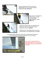
Page 22: ...ve pins into the holes and anchor the ABA to the concrete using a hammer as shown in photo 3 Simply butt the 10 lengths end to end until the perimeter of the greenhouse is complete Do not attach the ABA to the column post or leg using Tek screws the screw heads will interfere with the P C S S covering 1 2 3 VIEW AT THE CORNER ONLY USE THIS METHOD OF SECURING ABA IF YOU HAVE A CONCRETE SLAB OR CONC...

Page 23: ...connector When flush apply washer lock nut Do not tighten bolts at this point ridge base profile bolt track 5 Connecting additional pieces of ridge base identify Aluminum Splice Plates Slide 2 additional 1 4 x 2 1 2 bolts into the bolt track at the end of the already installed piece of ridge base place the splice plate onto those bolts apply washers lock nuts and firmly tighten splice plate to rid...

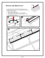
Page 24: ... hold the polycarbinate in place at the peak of the greenhouse ridge cap 1 Identify Ridge Cap Extrusion 2 Place on top and flush with the end of the ridge base 3 Secure with one 14 x 3 tek screw approximately 2 from end then every 4 0 apart 1 2 3 ridge base 14 x 3 tek screw w washer ridge cap approx 2 4 0 4 0 Page 22 ...

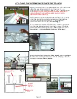
Page 25: ... rafter extrusion over the flange of the ridge base extrusion allowing the tek screw in the ridge base extrusion to fit inside the slot located on the underside of the intermediate rafter extrusion See photo 1 Fig E Be sure that the Intermediate rafter extrusion is pushed up against the hip of the ridge base extrusion and insert two tek screws through the Intermediate rafter and through the flange...

Page 26: ...w See photos 1 2 Stand the P C S S in place and attach it the end wall framing using the 12 x 1 1 2 tek screws with the oversize washers provided The screws will need to be spaced approximately 18 apart When joining two sheets together you must attach a piece of H splice after each sheet across the width of the house The H splice attaches to the endwall framing using the 12 x 1 1 4 tek screws prov...

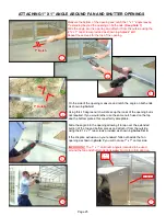
Page 27: ...g but is not required If you would rather use the same notch used on the top and the bottom pieces this is perfectly acceptable Slide the angle into the opening allowing it to lap over the extended portion of the top and bottom pieces and attach it from the outside using the 12 x 1 tek screws provided as shown in photos 5 6 If the H splice extrusion on your endwall falls out beside the fan opening...

Page 28: ...g Butt the end rafter extrusion up to ridge base extrusion and insert two screws into the end rafter extrusion through the flange of the ridge base extrusion as shown in photo 2 Also see Fig F Note The groove under the end rafter extrusion is not large enough to except the tek screw in the ridge base flange as was with the intermediate rafter extrusion End Rafter Extrusions Lip Working your way do...

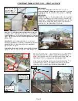
Page 29: ... K Peal off the protective film and attach the P C S S sheeting to the ABA and the sidewall horizontal purlin using the 5 16 x 1 1 4 tek screws approximately 18 apart Be sure that the correct side of the sheet is facing outward Repeat the procedure for the second sheet by inserting the sheet upward into the eave extrusion first then sliding the sheet over into the H splice channel Now slide the H ...

Page 30: ...the base of the structure Attach using 5 16 x 1 1 4 tek screws approximately 24 apart Lap each section of 1 x 1 approximately 2 to 3 as you continue around the perimeter of the structure Use the same process for notching the corners as you did with the 2 x 3 ABA 2 to 3 Lap 5 16 x 1 1 4 Tek Screws Approximatley 24 Apart 2 x 3 1 x 1 2 x 3 Base Angle 1 x 1 Base Angle Page 28 ...

Page 31: ...lashing Identify the 2 x 3 aluminum flashing the same as the base angle we used earlier Using tin snips or a jig saw cut the corner flashing to length and trim the top end to fit as neat as possible Attach the corner trim using Tek Screws with washers Page 29 ...

Page 32: ...is not necessary to place the sheet on a saw horse Slide the sheet downward a few inches and cut using a skill saw or jig saw Now slide the sheet back up between the ridge base and ridge cap slightly buckle the sheet upward and allow the sheet to fall into the eave extrusion channel USE EXTREME CAUTION WHEN CUTTING THE P C S S After each roof panel is in place flip the P C S S support brackets up ...

Page 33: ...on using a hack saw See photo 3 VERY IMPORTANT Once all the P C S S roof panels have been installed you must insert a tek screw through each of the P C S S support brackets into the purlins Failure to do so could result in structure failure in severe weather conditions Finish off the end walls by capping each gable end peak using a peak cap Allow the 1 1 2 flange of the peak cap to slide between t...

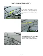
Page 34: ...BLY OR TRUSS CHORD USING TEK SCREWS SCREW THE CHAINS DIRECTLY TO THE SIDE OF THE BOW ASSEMBLY AS ILLUSTRATED IN PHOTOS 1 2 THE HANGING BRACKETS CAN ALSO BE USED TO ATTACH THE HAF FANS TO A TRUSS CHORD WHETHER IT BE SQUARE RECTANGLE OR ROUND TUBING AS SHOWN IN PHOTO 3 TEK SCREWS TEK SCREWS Page 32 ...

Page 35: ...overheating and causing the thermostats to loose their calibration Thermostats will loose calibration if temperatures exceed 120 deegrees F FAILURE TO PROPERLY VENTILATE THE GREENHOUSE WILL RESULT IN THERMOSTST DAMAGE THIS IS NOT COVERED BY THE MANUFACTURER S WARRENTY After you have completed the greenhouse use clear caulking to seal any places water might leak We recommend drilling weep holes in ...

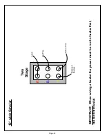
Page 36: ...R B Y Two Stage power Motorized Shutters Exhaust Fan HAF fan IMPORTANT When wiring a heater the power must be run to heater first not the thermostat 12 wide Scholar Page 34 ...

Reviews: