RIX Industries
040910-01
Page 1
Chapter 1 - Compressor Overview
1.1
Introduction
This manual is intended to provide all necessary information and documentation pertinent to the
installation, operation, and maintenance of the RIX compressor family 2PS-15—models 2PS-15-
115, 2PS-15-220 & 2PS-15-230. Ensure all operators of this compressor package read and
understand the entire manual prior to installation, operation, and/or servicing. All servicing shall
be performed only by trained and qualified personnel.
1.2
Description
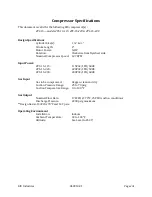
This is a 2 stage, 2 cylinder, air-cooled, oil-less compressor. This package is approximately 16
inches wide by 20.5 inches long by 29 inches tall and weighs approximately 172 lbs. See
Compressor Specifications
for design operating pressures, flow rate, and gas type. Note the flow
rate will vary with the suction pressure, temperature, and compressor condition. This unit was
packaged by RIX as a ready to operate package with control and safety devices.
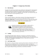
WARNING
Pneumatic energy hazard. Unit is designed to compress and store
high pressure gas. When pneumatic energy is released in an
uncontrolled manner, individuals may be crushed or struck by
moving machinery, equipment, or other items. If maintenance is
attempted on a pressured line without isolating the line and relieving
pressure, the sudden release of pressure can propel fittings or
rupture lines or vessels. Ensure unit is depressurized and locked out
prior to performing any maintenance.
1.3
Cooling
Due to the heat generated during compression it is necessary to cool both the compression
cylinders and the compressed gas. Cooling fans are installed to blow air over the compression
assemblies and then route the air over the cooling coils. Ambient cooling air is required to be within
the range given in
Compressor Specifications
. Cooler air is desirable as it will increase
compressor component life.
1.4
Gas Compression
RIX compressors are designed to safely compress gas without cylinder oil lubrication. Teflon based
piston rings are used in all stages. Since oil is not used in the compression cylinders, the
compressor will not contaminate the compressed gas; however, it is the responsibility of the user to
ensure that clean gas is supplied to the compressor suction at all times. A small amount of inert
piston ring dust will pass into the gas stream; this can be filtered out if desired.
Summary of Contents for 2PS-15-115
Page 37: ...RIX Industries 040910 01 Page 28 FIGURE 1 COMPRESSOR CROSS SECTION FASTENER DETAIL ...
Page 38: ...RIX Industries 040910 01 Page 29 FIGURE 2 COMPRESSOR CROSS SECTION PUMP DETAIL ...
Page 39: ...RIX Industries 040910 01 Page 30 FIGURE 3 1ST STAGE VALVE DETAIL ...
Page 40: ...RIX Industries 040910 01 Page 31 FIGURE 4 2ND STAGE VALVE DETAIL ...
Page 41: ...RIX Industries 040910 01 Page 32 FIGURE 5 EXTERIOR FASTENER DETAIL ...
Page 42: ...RIX Industries 040910 01 Page 33 FIGURE 6 MOTOR AND CONTROL BOX MOUNTING ...
Page 43: ...RIX Industries 040910 01 Page 34 FIGURE 7 SUCTION PLUMBING DETAIL ...
Page 44: ...RIX Industries 040910 01 Page 35 FIGURE 8 INTERSTAGE PLUMBING DETAIL ...
Page 45: ...RIX Industries 040910 01 Page 36 FIGURE 9 FINAL DISCHARGE PLUMBING DETAIL ...
Page 46: ...RIX Industries 040910 01 Page 37 FIGURE 10 COOLING FAN SUB ASSEMBLY DETAIL ...
Page 47: ...RIX Industries 040910 01 Page 38 FIGURE 11 BELT INSTALLATION DETAIL ...
Page 48: ...RIX Industries 040910 01 Page 39 FIGURE 12 GUARD MOUNTING DETAIL ...
Page 49: ...RIX Industries 040910 01 Page 40 FIGURE 13 CONTROL BOX DETAIL 1 OF 2 ...
Page 50: ...RIX Industries 040910 01 Page 41 FIGURE 14 CONTROL BOX DETAIL 2 OF 2 ...
Page 51: ...RIX Industries 040910 01 Page 42 FIGURE 15 CONTROL BOX WIRING DIAGRAM ...
Page 52: ...RIX Industries 040910 01 Page 43 FIGURE 16 ELECTRICAL SCHEMATIC ...
Page 53: ...RIX Industries 040910 01 Page 44 FIGURE 17 FLOW SCHEMATIC ...
Page 57: ......
Page 58: ......

