RIX Industries
040910-01
Page 11
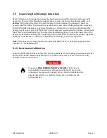
5.9
Connecting Rod Bearings Inspection
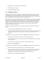
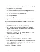
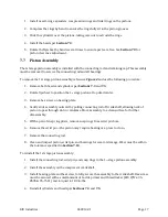
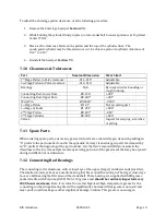
Every 2000 hours of running, the Connecting Rod bearings should be inspected and replaced if
necessary. To inspect the Needle Bearing (smaller), remove the Connecting Rod assembly – see
Section 7.12
, inspect the Wrist Pin outer diameter for deformation, if no bumps or dents are
present, insert the Wrist Pin through the needle bearing and rotate while holding the Connecting
Rod still. Notable bumpiness, roughness, knocking, or resistance to rotation would indicate this
bearing needs to be replaced. If the Wrist Pin outer diameter contains dents or bumps, replace both
the Wrist Pin and Needle Bearing. To inspect the Ball Bearing (larger), rotate the inner race of the
bearing by hand while holding the Connecting Rod still. Like before, notable bumpiness, roughness,
knocking, or resistance to rotation would indicate this bearing needs to be replaced.
Note:
if bearings are not being replaced, re-pack with (RIX P/N 45-110) Polyurea grease before
installation – see
Section 7.12
.
5.10
Instrument Calibration
Control instruments should be verified for accuracy annually. Pressure gauges, switches, and relief
valves can be bench tested on a hydro fixture to confirm the accuracy of each device. Use only
deionized water for these tests.
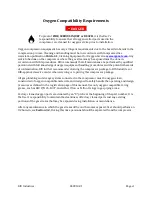
DANGER
To prevent
FIRE, SERIOUS INJURY or DEATH
, it is the User’s
responsibility to ensure that all oxygen wetted parts used in the
compressor are cleaned for oxygen service prior to installation. Use
only deionized water as unfiltered water may contaminate the
instrumentation.
Summary of Contents for 2PS-15-115
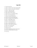
Page 37: ...RIX Industries 040910 01 Page 28 FIGURE 1 COMPRESSOR CROSS SECTION FASTENER DETAIL ...
Page 38: ...RIX Industries 040910 01 Page 29 FIGURE 2 COMPRESSOR CROSS SECTION PUMP DETAIL ...
Page 39: ...RIX Industries 040910 01 Page 30 FIGURE 3 1ST STAGE VALVE DETAIL ...
Page 40: ...RIX Industries 040910 01 Page 31 FIGURE 4 2ND STAGE VALVE DETAIL ...
Page 41: ...RIX Industries 040910 01 Page 32 FIGURE 5 EXTERIOR FASTENER DETAIL ...
Page 42: ...RIX Industries 040910 01 Page 33 FIGURE 6 MOTOR AND CONTROL BOX MOUNTING ...
Page 43: ...RIX Industries 040910 01 Page 34 FIGURE 7 SUCTION PLUMBING DETAIL ...
Page 44: ...RIX Industries 040910 01 Page 35 FIGURE 8 INTERSTAGE PLUMBING DETAIL ...
Page 45: ...RIX Industries 040910 01 Page 36 FIGURE 9 FINAL DISCHARGE PLUMBING DETAIL ...
Page 46: ...RIX Industries 040910 01 Page 37 FIGURE 10 COOLING FAN SUB ASSEMBLY DETAIL ...
Page 47: ...RIX Industries 040910 01 Page 38 FIGURE 11 BELT INSTALLATION DETAIL ...
Page 48: ...RIX Industries 040910 01 Page 39 FIGURE 12 GUARD MOUNTING DETAIL ...
Page 49: ...RIX Industries 040910 01 Page 40 FIGURE 13 CONTROL BOX DETAIL 1 OF 2 ...
Page 50: ...RIX Industries 040910 01 Page 41 FIGURE 14 CONTROL BOX DETAIL 2 OF 2 ...
Page 51: ...RIX Industries 040910 01 Page 42 FIGURE 15 CONTROL BOX WIRING DIAGRAM ...
Page 52: ...RIX Industries 040910 01 Page 43 FIGURE 16 ELECTRICAL SCHEMATIC ...
Page 53: ...RIX Industries 040910 01 Page 44 FIGURE 17 FLOW SCHEMATIC ...
Page 57: ......
Page 58: ......

