RIX Industries
040910-01
Page 14
Chapter 7 - Corrective Maintenance
7.1
Introduction
This chapter provides instructions for adjustments and repairs to the compressor package. Where
special tools are required, they are called out in the applicable paragraph. When installing new O-
rings lightly lubricate them with an oxygen compatible O-ring grease such as RIX P/N 45-1007.
DANGER
Before performing any maintenance, the compressor power supply
should be locked
Out of Service
to prevent starting which could cause
injury to personnel or damage to the equipment. Relieve all internal
pressure and allow piping to cool before repair.
7.2
Gas Leak Check
After maintenance or if flow capacity is degraded, all compression end seams should be examined
for leaks. Leak testing requires that the unit be pressurized, and therefore running or recently run.
A soapy solution in a squirt bottle is one method of locating leaks. This test is simplified if the
compressor is allowed to cool, then restarted immediately prior to conducting the leak test; hot
components can boil away the soap solution making detection of leaks difficult or impossible.
Observe for the formation of bubbles. Large leaks may blow the solution away as it is applied, and
therefore must be detected by sound, being careful of hot gases and plumbing. O-ring joints
normally cannot be corrected by additional tightening, in most cases a new O-ring is required.
Always inspect O-ring sealing surfaces for defects. Ensure the proper durometer O-ring is used.
Note
: See A5089 “O-ring Installation & Material Information” in the appendix for more information
about O-rings.
7.3
Cylinder Heads
To remove the cylinder heads, follow the instructions below:
1.
Disconnect plumbing from the head.
2.
Note the orientation of the head to ensure proper reassembly.
3.
Remove the nuts using an alternating cross pattern.
4.
Lift the head from the cylinder.
To reinstall the cylinder heads, reference
Figure 1
and follow the instructions below:
1.
Install a new O-ring at the top of the cylinder.
2.
Correctly orient the head with the cylinder and install.
Summary of Contents for 2PS-15-115
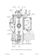
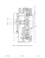
Page 37: ...RIX Industries 040910 01 Page 28 FIGURE 1 COMPRESSOR CROSS SECTION FASTENER DETAIL ...
Page 38: ...RIX Industries 040910 01 Page 29 FIGURE 2 COMPRESSOR CROSS SECTION PUMP DETAIL ...
Page 39: ...RIX Industries 040910 01 Page 30 FIGURE 3 1ST STAGE VALVE DETAIL ...
Page 40: ...RIX Industries 040910 01 Page 31 FIGURE 4 2ND STAGE VALVE DETAIL ...
Page 41: ...RIX Industries 040910 01 Page 32 FIGURE 5 EXTERIOR FASTENER DETAIL ...
Page 42: ...RIX Industries 040910 01 Page 33 FIGURE 6 MOTOR AND CONTROL BOX MOUNTING ...
Page 43: ...RIX Industries 040910 01 Page 34 FIGURE 7 SUCTION PLUMBING DETAIL ...
Page 44: ...RIX Industries 040910 01 Page 35 FIGURE 8 INTERSTAGE PLUMBING DETAIL ...
Page 45: ...RIX Industries 040910 01 Page 36 FIGURE 9 FINAL DISCHARGE PLUMBING DETAIL ...
Page 46: ...RIX Industries 040910 01 Page 37 FIGURE 10 COOLING FAN SUB ASSEMBLY DETAIL ...
Page 47: ...RIX Industries 040910 01 Page 38 FIGURE 11 BELT INSTALLATION DETAIL ...
Page 48: ...RIX Industries 040910 01 Page 39 FIGURE 12 GUARD MOUNTING DETAIL ...
Page 49: ...RIX Industries 040910 01 Page 40 FIGURE 13 CONTROL BOX DETAIL 1 OF 2 ...
Page 50: ...RIX Industries 040910 01 Page 41 FIGURE 14 CONTROL BOX DETAIL 2 OF 2 ...
Page 51: ...RIX Industries 040910 01 Page 42 FIGURE 15 CONTROL BOX WIRING DIAGRAM ...
Page 52: ...RIX Industries 040910 01 Page 43 FIGURE 16 ELECTRICAL SCHEMATIC ...
Page 53: ...RIX Industries 040910 01 Page 44 FIGURE 17 FLOW SCHEMATIC ...
Page 57: ......
Page 58: ......

