RIX Industries
040910-01
Page 20
compatible and must not come into contact with any gas wetted surfaces within the assembly, i.e.,
compression rings, lingers, piping, fittings, etc.
To replace the Connecting Rod Bearings:
1.
Remove the piston assembly per
Section 7.7
.
2.
With a pair of snap ring pliers, remove the snap rings from the wrist pin grooves.
3.
Remove the wrist pin by pushing it through the needle bearing from one side of the piston
to the other, which may require a press. The piston may also require heating to allow the
wrist pin to be removed.
4.
Remove the connecting rod from the piston assembly.
5.
Remove the retaining plate from the ball bearing (larger closed eye).
6.
Press the needle bearing out of the small end of the connecting rod (smaller closed eye).
7.
Note: the large end connecting rod ball bearing was installed with a shrink-fit. Therefore, to
remove the ball bearing, the assembly should first be heated to 300° F and pressed lightly.
This will allow the ball bearing to slide out of its housing.
8.
To install a new ball bearing, first heat the connecting rod to 300° F. Once heated, lay the
large end of the connecting rod on a flat surface, then slide the ball bearing into the bore and
allow to cool for final fitment.
9.
Pack ball bearing full of RIX P/N 45-110 grease and reinstall the retaining plate.
10.
To install a new needle bearing, first assure the bearing is packed with RIX PN 45-110
grease, then press into the small end of the connecting rod. Note: Be sure to press the
stamped end of the bearing (with identification markings).
11.
Assemble the connecting rod into the piston assembly by pushing the wrist pin through the
bore in the rod, through the needle bearing and then back through the other side of the bore
in the rod.
12.
Reinstall snap rings into their grooves.
Summary of Contents for 2PS-15-115
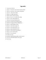
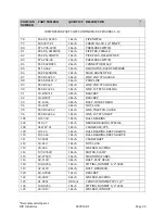
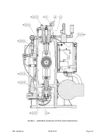
Page 37: ...RIX Industries 040910 01 Page 28 FIGURE 1 COMPRESSOR CROSS SECTION FASTENER DETAIL ...
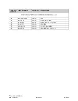
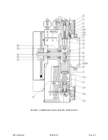
Page 38: ...RIX Industries 040910 01 Page 29 FIGURE 2 COMPRESSOR CROSS SECTION PUMP DETAIL ...
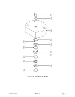
Page 39: ...RIX Industries 040910 01 Page 30 FIGURE 3 1ST STAGE VALVE DETAIL ...
Page 40: ...RIX Industries 040910 01 Page 31 FIGURE 4 2ND STAGE VALVE DETAIL ...
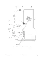
Page 41: ...RIX Industries 040910 01 Page 32 FIGURE 5 EXTERIOR FASTENER DETAIL ...
Page 42: ...RIX Industries 040910 01 Page 33 FIGURE 6 MOTOR AND CONTROL BOX MOUNTING ...
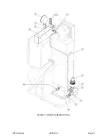
Page 43: ...RIX Industries 040910 01 Page 34 FIGURE 7 SUCTION PLUMBING DETAIL ...
Page 44: ...RIX Industries 040910 01 Page 35 FIGURE 8 INTERSTAGE PLUMBING DETAIL ...
Page 45: ...RIX Industries 040910 01 Page 36 FIGURE 9 FINAL DISCHARGE PLUMBING DETAIL ...
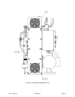
Page 46: ...RIX Industries 040910 01 Page 37 FIGURE 10 COOLING FAN SUB ASSEMBLY DETAIL ...
Page 47: ...RIX Industries 040910 01 Page 38 FIGURE 11 BELT INSTALLATION DETAIL ...
Page 48: ...RIX Industries 040910 01 Page 39 FIGURE 12 GUARD MOUNTING DETAIL ...
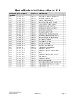
Page 49: ...RIX Industries 040910 01 Page 40 FIGURE 13 CONTROL BOX DETAIL 1 OF 2 ...
Page 50: ...RIX Industries 040910 01 Page 41 FIGURE 14 CONTROL BOX DETAIL 2 OF 2 ...
Page 51: ...RIX Industries 040910 01 Page 42 FIGURE 15 CONTROL BOX WIRING DIAGRAM ...
Page 52: ...RIX Industries 040910 01 Page 43 FIGURE 16 ELECTRICAL SCHEMATIC ...
Page 53: ...RIX Industries 040910 01 Page 44 FIGURE 17 FLOW SCHEMATIC ...
Page 57: ......
Page 58: ......


