background image


*Recommended Spares 

RIX Industries 

040910-01 

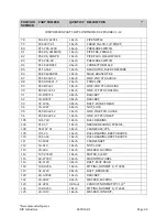
Page 23 

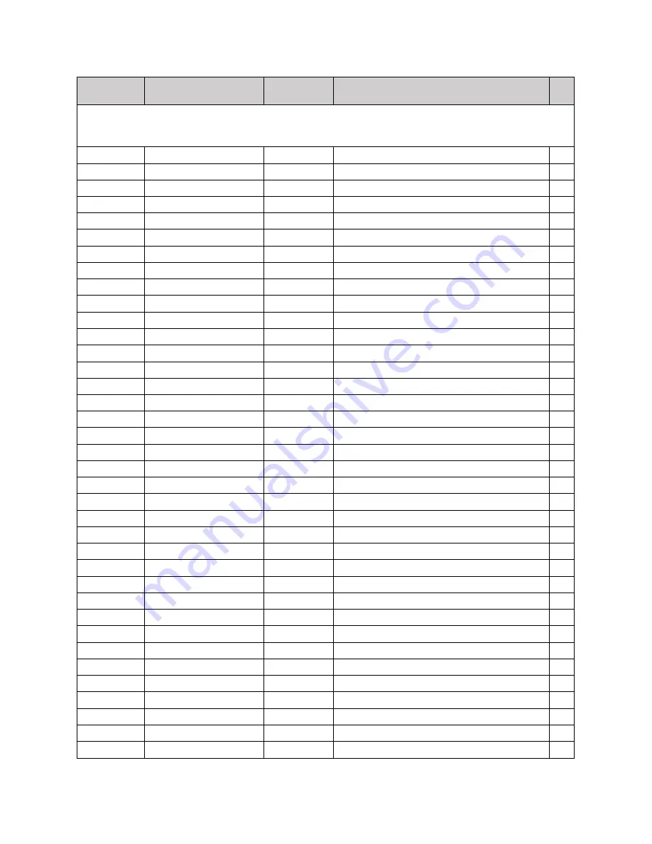
POSITION 

NUMBER


PART NUMBER 


QUANTITY


DESCRIPTION


*


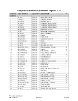
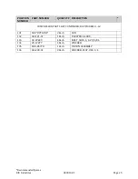
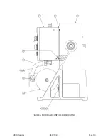
COMPRESSOR PARTS LIST CONTINUED; REF FIGURES 1 -12 


39 

22-A7797 

AS REQ’D 

SHIM 

40 

X10-B11412 

1 EACH 

MANIFOLD, 2PS 


41 

20-1003 

20 EACH 

WASHER, FLAT SAE 


42 

32-4136 

14 EACH 

BOLT, HEX HEAD, 


43 

X10-A7946 

1 Each 

MANIFOLD, SUCTION 2PS 


44 

32-1134 

4 Each 

BOLT, HEX HEAD, 


45 

X10-A7947 

1 Each 

MANIFOLD, DISCHARGE 2PS 


46 

38-C2384-1 

1 Each 

COVER PLATE, C'CASE 


48 

156-153 

2 Each 

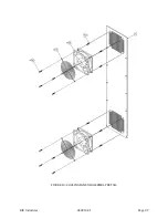
GUARD, FAN 


49 

32-1156 

7 Each 

BOLT, HEX HEAD, 


50 

34-6261 

16 Each 

SCREW, PAN HEAD, PHILLIPS 


51 

61-27216 

7 Each 

WIRE HOLDER, 


53 

X515-852 

1 Each 

RELIEF VALVE 


54 

X515-851 

1 Each 

RELIEF VALVE 


55 

X515-855 

1 Each 

RELIEF VALVE 


56 

X74-401 

3 Each 

GAUGE SNUBBER 


57 

X54P-1/4CDSS 

3 Each 

PIPE ELBOW, STREET 


58 

X60-824 

1 Each 

GAUGE, PRESSURE 


59 

X60-826 

1 Each 

GAUGE, PRESSURE 


60 

X60-828 

1 Each 

GAUGE, PRESSURE 


61 

SEE "OPTIONS" 

1 Each 

MOTOR SHEAVE 


62 

91-A4423-1 

1 Each 

KEY, SQUARE, 


63 

11-100SK 

1 Each 

BUSHING, SK SERIES, 


64 

36-15521 

1 Each 

FLYWHEEL, 6J140-SK 


65 

41-520J6 

1 Each 

BELT, J-SECTION, 

66 

041115-01 

1 Each 

BACK COVER, BELTGUARD 


67 

156-D2576-2 

1 Each 

FRONT COVER, BELTGUARD 


68 

156-D2576-3 

1 Each 

LOWER PANEL, BELTGUARD 


69 

53-4098 

2 Each 

NUT, HEX 


70 

34-1002 

5 Each 

SCREW, SHEET METAL 


71 

X54P-44FBUSS 

4 Each 

CONNECTOR, MALE 


72 

X54P-1/4MROSS 

2 Each 

PIPE TEE, MALE RUN 


73 

X54P-44CBUSS 

3 Each 

ELBOW, MALE, 1/4 TUBE TO 


74 

X55-D2621-6 

1 Each 

LINE, FILTER INLET 


75 

XA77-505 

2 Each 

FILTER 

76 

X55-D2621-5 

1 Each 

LINE, 2ND STG INLET 


77 

X54P-4CBUSS 

1 Each 

ELBOW, MALE, 1/4 TUBE TO 


Summary of Contents for 2PS-15-115

Page 1: ... 15 220 2PS 15 230 Rix Industries 2 Stage Oil Less Air Cooled Oxygen Compressor This manual including information and products referenced herein to be provided by Seller Products are subject to U S export control laws and will not be resold re exported or retransferred directly or indirectly to any person in violation of U S Export Administration Regulations ...

Page 2: ...AL RELEASE A 07 12 21 ICB Parts List See ECO 011049 B 10 14 21 AV Parts List Fig 12 See ECO 011231 C 10 26 21 AV 4 5 Discharge RV Setpoint Correction D 01 21 22 AV viii 6 8 Appendix Specification changes for new minimum suction pressure new interface drawing E 04 13 22 AV ii iii 9 11 19 44 Addition of Sections 5 9 and 7 12 ...

Page 3: ... Start Up 5 3 4 Normal Operating Conditions 6 Chapter 4 Control System 7 4 1 System Overview 7 4 2 Manual Operation Mode 7 4 3 Auto Operation Mode 7 4 4 Control logic Description 8 4 5 Safety Device Set Points 8 Chapter 5 Routine Inspection Scheduled Maintenance 9 5 1 Introduction 9 5 2 Routine Inspection 9 5 3 Scheduled Maintenance 9 5 4 Gas Filter Service 10 5 5 Compressor Valve Service 10 5 6 R...

Page 4: ...RIX Industries 040910 01 Page iii 7 7 Piston Assembly 17 7 8 Main Bearings 18 7 9 Piston to Head Clearance 18 7 10 Clearances Tolerances 19 7 11 Spare Parts 19 Appendix 21 ...

Page 5: ...ssor Model Family 2PS 15 Serial Number Note Parts recommended for routine service are indicated in the parts lists The customer is advised to maintain these parts at their facility or procure them in advance as lead times and availability can vary RIX also offers service and overhaul kits to support other scheduled maintenance requirements RIX is an AS9100C ISO9001 2008 registered company All comp...

Page 6: ...this equipment shall be installed and grounded in accordance with applicable codes and regulations 3 Before working on electrical equipment take steps to ensure system is de energized and will remain so while work is in progress All circuits not known to be DEAD must be considered LIVE and dangerous at all times WARNING This symbol means if the warning is not heeded it can cause death bodily injur...

Page 7: ...s of contamination RIX further recommends returning the compressor package to RIX Industries or RIX approved service center when servicing or repairing this compressor package All gas plumbing and storage systems connected to the compressor must be oxygen clean constructed of oxygen compatible materials and designed to safely handle the operating and design pressures as defined in the registration...

Page 8: ...ion Seller shall at its option either repair or replace its part at the original F O B point of delivery Defective items must be held for Seller s inspection and returned to the original F O B point upon request C With respect to parts not manufactured or services not performed by Seller Seller assigns to Buyer whatever warranty Seller receives from the Supplier of such parts or services However S...

Page 9: ...essor Speed 127 RPM Input Power 2PS 15 115 115VAC 1PH 60HZ 2PS 15 220 220VAC 1PH 50HZ 2PS 15 230 230VAC 1PH 60HZ Gas Input Gas to be compressed Oxygen clean and dry Suction Pressure Range 25 to 70 psig Suction Temperature Range 0 to 100 F Gas Output Nominal Flow Rate 17 SCFH 70 F 25 PSIG suction conditions Discharge Pressure 2200 psig maximum Design basis of SCFH is 70 F and 14 7 psia Operating En...

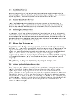
Page 10: ...released in an uncontrolled manner individuals may be crushed or struck by moving machinery equipment or other items If maintenance is attempted on a pressured line without isolating the line and relieving pressure the sudden release of pressure can propel fittings or rupture lines or vessels Ensure unit is depressurized and locked out prior to performing any maintenance 1 3 Cooling Due to the hea...

Page 11: ... 5 Crankcase Lubrication This oil less compressor utilizes sealed bearings Oil less compressors contain absolutely no oil within the whole compressor package removing the likelihood of any oil carry over thus eliminating contamination ...

Page 12: ...e plumbing must be large enough to pass design flow at lowest expected back pressure without choking the flow User s suction and discharge plumbing should be designed to accommodate compressor vibration CAUTION If flexible lines are used user is responsible to secure those lines to prevent whipping in case of breakage Safety relief valves are installed on the compressor at each stage of compressio...

Page 13: ...e If the compressor is taken out of service provision should be made to protect against corrosion At a minimum gas suction and discharge lines should be capped and belt tension relieved The compressor should be rotated at least once every month In corrosive environments the unit should be nitrogen purged After extended storage or if stored without climate control the compressor heads and valves sh...

Page 14: ... oxygen 2 Run compressor at conditions stated in Compressor Specifications using a closed loop if necessary 3 Slowly inject oxygen into the inlet while venting the compressor discharge until the unit is running on pure oxygen This step should take at least 30 minutes This will allow any organic materials left in the system to safely oxidize 3 3 Start Up After performing the pre startup system insp...

Page 15: ...rom hitting the 2nd stage valve during normal operation Stage Pressure psig Temperature F Suction 25 70 70 Interstage 300 600 300 Discharge 1500 2200 225 CAUTION Cylinder heads and discharge lines are hot Touching any part of the cylinder heads or discharge lines can cause burns It is recommended that the Service Log in the appendix of this manual be used to note operating pressures temperatures a...

Page 16: ... both suction and discharge pressure A HOA Hand Off Auto switch is located on the front of the control box and allows operator choice of modes A remote contact is installed in the control box and can tied into to an ancillary control system for remote start stop signal line use etc If such control is desired remove pink jumper wired between contact blocks 1 and 3 in the control box 4 2 Manual Oper...

Page 17: ...tion or discharge switch will break current to the coil TDR which will stop the drive motor 4 The compressor may also be run in the automatic mode by selecting AUTO on the HOA switch All features are the same as described above except that after the inlet or discharge switch shut down the unit the compressor will automatically restart when the switches are moved to the closed setting The compresso...

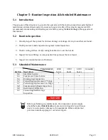
Page 18: ...g air flow Verify cooling fans blow air over the heads 4 Inspect for loose fittings or components Fix any issues that are found 5 Inspect for unusual noises or vibrations 5 3 Scheduled Maintenance Section Time Interval Operation 2000 hours 3000 hours 4000 hours Annually 5 4 Gas Filter Service 5 5 Compressor Valve Service 5 6 Running Gear Inspection 5 7 Piston Ring Replacement 1st Stage 5 7 Piston ...

Page 19: ...ings expanders and riders should be replaced As the compression rings wear their ability to seal is diminished Excessive wear will result in lower compressor capacity more frequent compressor operation and unnecessary wear on other components With extreme wear the compressor will not be able to compress to the design pressure If the compressor starts and stops more frequently fails to make pressur...

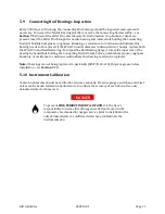
Page 20: ...e Ball Bearing larger rotate the inner race of the bearing by hand while holding the Connecting Rod still Like before notable bumpiness roughness knocking or resistance to rotation would indicate this bearing needs to be replaced Note if bearings are not being replaced re pack with RIX P N 45 110 Polyurea grease before installation see Section 7 12 5 10 Instrument Calibration Control instruments s...

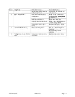
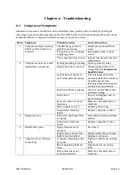
Page 21: ...ssor Specifications Lack of back pressure in user s downstream piping If downstream should be pressurized look for leaks in downstream system If downstream should not be pressurized no problem Restricted filters or piping Clean or replace filters and upstream piping Belt is loose Inspect and tighten belt to proper tension Excessive piston to head clearance Measure and adjust piston clearance Pisto...

Page 22: ...ssure to range stated in Compressor Specifications Fans are inoperative Repair or replace fans High ambient temperature Ensure ambient temperature is within design limits Compressor valves have failed Replace compressor valves 7 Loud metallic knocking Piston is hitting valve Measure and adjust piston clearance Replace back pressure regulator 8 Ticking noise from cylinder head Compressor valve is w...

Page 23: ...f the compressor is allowed to cool then restarted immediately prior to conducting the leak test hot components can boil away the soap solution making detection of leaks difficult or impossible Observe for the formation of bubbles Large leaks may blow the solution away as it is applied and therefore must be detected by sound being careful of hot gases and plumbing O ring joints normally cannot be ...

Page 24: ...nish To remove and disassemble both the 1st and 2nd stage compressor valves follow the instructions below 1 Remove the head per Section 7 3 and move to a flat clean surface 2 Separate all components and discard the used O rings Note a soft punch may be used to aid with disassembly by removing the plug at the top of head and pushing through the now open port To reinstall the 1st stage compressor va...

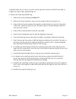
Page 25: ... 1 Remove the head per Section 7 3 2 Rotate the flywheel to position the 1st stage piston at bottom dead center 3 Slide 1st stage cylinder off piston using caution to prevent side loading the piston rod assembly and damage to the shims It may be necessary to either lean back or elevate the compressor to complete this task 4 Remove 2nd stage guide cylinder and liner 5 Clean and inspect the cylinder...

Page 26: ...on at top dead center 3 Remove hex screw on bearing plate 4 Gently slide assembly outward by pulling connecting rod off crankshaft allowing neck of piston to pass through slot in crankcase Move assembly to a clean surface for further disassembly 5 With a pair of snap ring pliers remove snap rings from wrist pin bore 6 Remove the wrist pin the piston may require heating or a press to do so 7 Remove...

Page 27: ...o the crankcase Heating may be required 3 Install outboard bearing flywheel side 4 Install new lock washer with bearing nut torque to 50 ft lbs and bend lock washer tab to secure nut 5 Reinstall piston assembly cylinders and heads per Sections 7 7 7 5 and 7 3 7 9 Piston to Head Clearance The piston to head clearance of both stages is factory set and should not need adjustment unless one or more pa...

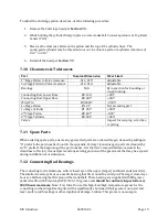
Page 28: ...ing scratches or pitting 7 11 Spare Parts When ordering spare parts ensure any gas wetted parts are ordered Oxygen cleaned by adding an X prefix to the part number found in the appendix Factory cleaned oxygen parts are denoted by an X prefix at the beginning of the part number It is the User s responsibility to maintain the cleanliness of factory cleaned parts and any existing portions of the gas ...

Page 29: ...ng rod ball bearing was installed with a shrink fit Therefore to remove the ball bearing the assembly should first be heated to 300 F and pressed lightly This will allow the ball bearing to slide out of its housing 8 To install a new ball bearing first heat the connecting rod to 300 F Once heated lay the large end of the connecting rod on a flat surface then slide the ball bearing into the bore an...

Page 30: ...ion Plumbing Detail 9 Figure 8 Interstage Plumbing Detail 10 Figure 9 Final Discharge Plumbing Detail 11 Figure 10 Cooling Fan Sub Assembly Detail 12 Figure 11 Belt Installation Detail 13 Figure 12 Guard Mounting Detail 14 Figure 13 Control Box Detail 1 of 2 15 Figure 14 Control Box Detail 2 of 2 16 Figure 15 Control Box Wiring Diagram 17 Figure 16 Electrical Schematic 18 Figure 17 Flow Schematic ...

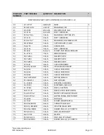
Page 31: ...AT SAE 17 X18 C1791 10G 2 EACH RING PISTON 1 1 4 DIA 2 18 X123 313 5 2 EACH O RING 2 19 X18 B2117 2G 2 EACH RING RIDER 1 1 4 DIA 2 20 X54P 4P50NSS 2 EACH PLUG ST THD HEX HEAD 21 X123 904 3 2 EACH O RING TEFLON 3 22 31 B7617 1 EACH RETAINER RING 23 X15 A4151 1 EACH VALVE PART 24 X123 018 5 95 3 EACH O RING VITON 95 DURO 4 25 X15 B2706 2 EACH REED VALVE 26 X15 B3570 1 EACH VALVE SEAT 27 X17 758 2 EA...

Page 32: ... 855 1 Each RELIEF VALVE 56 X74 401 3 Each GAUGE SNUBBER 57 X54P 1 4CDSS 3 Each PIPE ELBOW STREET 58 X60 824 1 Each GAUGE PRESSURE 59 X60 826 1 Each GAUGE PRESSURE 60 X60 828 1 Each GAUGE PRESSURE 61 SEE OPTIONS 1 Each MOTOR SHEAVE 62 91 A4423 1 1 Each KEY SQUARE 63 11 100SK 1 Each BUSHING SK SERIES 64 36 15521 1 Each FLYWHEEL 6J140 SK 65 41 520J6 1 Each BELT J SECTION 1 66 041115 01 1 Each BACK C...

Page 33: ... COOLING 91 40 B5871 1 4 Each BRACKET 92 40 B5871 2 Each BRACKET 93 32 1056 4 Each BOLT SOCKET HEAD 94 53 4087 4 Each NUT LOCK 95 X55 D2621 2 1 Each LINE INLET PR GAUGE 96 X55 D2621 4 1 Each LINE 1ST STG INLET 105 181 728 1 Each BALL BEARING 106 X181 7 1 Each NEEDLE BEARING SPECIAL 108 041167 01 1 Each CRANKCASE 2PS 109 181 26 1 Each BALL BEARING DEEP GROOVE 110 181 604 1 Each BALL BEARING DEEP GR...

Page 34: ... QUANTITY DESCRIPTION COMPRESSOR PARTS LIST CONTINUED REF FIGURES 1 12 131 SEE OPTIONS 2 Each FAN 132 041121 01 1 Each ELECTRICAL BOX 133 32 22809 4 Each BOLT SHCS 1 4 20 5 8 L 134 20 12877 4 Each WASHER 135 XA8 B5778 1 Each PISTON ASSEMBLY 136 041209 01 3 Each WASHER FLAT USS 1 4 ...

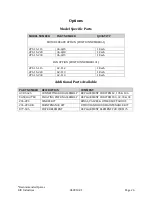
Page 35: ...ITION NUMBER 131 2PS 15 115 42 112 1 Each 2PS 15 220 42 113 1 Each 2PS 15 230 42 113 1 Each Additional Parts Available PART NUMBER DESCRIPTION COMMENT A7 B5625 CONNECTING ROD ASSEMBLY REPLACEMENT FOR ITEMS 2 105 106 XA508 A7783 FLOATING PISTON ASSEMBLY REPLACEMENT FOR ITEMS 30 32 33 34 204 2PS SPARES KIT RINGS VALVES OTHER SOFT GOODS 204 2PS 8K MAINTENANCE KIT 8 THOUSAND HOUR MAINTENANCE KIT X77 5...

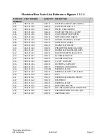
Page 36: ...0 041121 410 1 EACH PUSHBUTTON MOM BLK FLUSH 411 041121 411 1 EACH LEGEND PLATE HAND OFF AUTO 412 041121 412 1 EACH SELECTOR SWITCH HEAD 3 POS 413 041121 413 1 EACH NC CONTACT BLOCK 414 041121 414 1 EACH NO CONTACT BLOCK 415 041121 415 2 EACH 1 2 NPT CORD GRIP 416 041121 416 2 EACH LOCKNUT O RING KIT 417 041121 417 2 EACH TERMINAL END ANCHOR 418 041121 418 12 EACH TERMINAL BLOCK 419 041121 419 1 E...

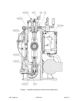
Page 37: ...RIX Industries 040910 01 Page 28 FIGURE 1 COMPRESSOR CROSS SECTION FASTENER DETAIL ...

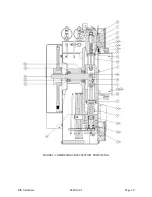
Page 38: ...RIX Industries 040910 01 Page 29 FIGURE 2 COMPRESSOR CROSS SECTION PUMP DETAIL ...

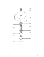
Page 39: ...RIX Industries 040910 01 Page 30 FIGURE 3 1ST STAGE VALVE DETAIL ...

Page 40: ...RIX Industries 040910 01 Page 31 FIGURE 4 2ND STAGE VALVE DETAIL ...

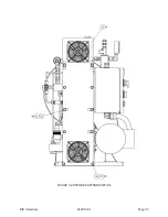
Page 41: ...RIX Industries 040910 01 Page 32 FIGURE 5 EXTERIOR FASTENER DETAIL ...

Page 42: ...RIX Industries 040910 01 Page 33 FIGURE 6 MOTOR AND CONTROL BOX MOUNTING ...

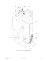
Page 43: ...RIX Industries 040910 01 Page 34 FIGURE 7 SUCTION PLUMBING DETAIL ...

Page 44: ...RIX Industries 040910 01 Page 35 FIGURE 8 INTERSTAGE PLUMBING DETAIL ...

Page 45: ...RIX Industries 040910 01 Page 36 FIGURE 9 FINAL DISCHARGE PLUMBING DETAIL ...

Page 46: ...RIX Industries 040910 01 Page 37 FIGURE 10 COOLING FAN SUB ASSEMBLY DETAIL ...

Page 47: ...RIX Industries 040910 01 Page 38 FIGURE 11 BELT INSTALLATION DETAIL ...

Page 48: ...RIX Industries 040910 01 Page 39 FIGURE 12 GUARD MOUNTING DETAIL ...

Page 49: ...RIX Industries 040910 01 Page 40 FIGURE 13 CONTROL BOX DETAIL 1 OF 2 ...

Page 50: ...RIX Industries 040910 01 Page 41 FIGURE 14 CONTROL BOX DETAIL 2 OF 2 ...

Page 51: ...RIX Industries 040910 01 Page 42 FIGURE 15 CONTROL BOX WIRING DIAGRAM ...

Page 52: ...RIX Industries 040910 01 Page 43 FIGURE 16 ELECTRICAL SCHEMATIC ...

Page 53: ...RIX Industries 040910 01 Page 44 FIGURE 17 FLOW SCHEMATIC ...

Page 54: ... 2PS 15 230 O2 230V 60HZ 1PH 17 SCFH 4 5A BELTGUARD REMOVED FOR CLARITY 3 2 INTERFACE DRAWING 20 65 4 00 A 1 06 1 4 18 NPT INLET PORT Ø 25 A B LOW PRESSURE SWITCH 50 2 25 RELIEF VALVES 29 0 MAX 6 75 2X 1ST STAGE 13 25 2X 56 4X Ø 030 A B 20 5 MAX 16 0 MAX 2ND STAGE GAUGES FAN ELECTRICAL BOX HOA SWITCH START BUTTON RUNNING LIGHT HOUR METER MOTOR FLYWHEEL BUSHING CRANKSHAFT DRIVE SHEAVE 4 5 1 4 18 NP...

Page 55: ...ature grease such as Krytox or Christo Lube MGC 111 before installation Apply a thin coating by drawing the o ring through your fingers This will extend the life of the seal and simplify installation CAUTION O rings used in oxygen service must be lubed with an oxygen compatible grease RIX P N 45 1007 45 19220 or equivalent All o rings supplied for O2 service have an X prefix and are oxygen cleaned...

Page 56: ...djustment screw If the set point is on decreasing pressure then increase the pressure vacuum of the source starting at a point higher than the set point Step 3 Using the continuity tester and the pressure vacuum gauge determine the actuation point of the switch Step 4 If the actuation point is above the desired value turn the adjustment screw or knob per instructions in the pressure switch catalog...

Page 57: ......

Page 58: ......
Reviews: