ADJUSTMENT INSTRUCTIONS
Differential/Pressure/Vacuum Switch
General:
1. Check proof pressure of switch on name plate or catalog.
NEVER EXCEED THIS PROOF
PRESSURE.
2. Note the adjustable range of switch (increasing or decreasing pressure) as listed in the catalog or on the
name plate.
3. Check the catalog listing for actuation value of the switch.
To set the switch you need: 1. A pressure/vacuum source
2. A pressure/vacuum gauge
3. An electric continuity tester
CAUTION!
-ALWAYS CHANGE
PRESSURE SETTING GRADUALLY.
-ALWAYS check switch setting before making any adjustments.
Step 1
.
Determine if the pressure/vacuum set point is on increasing or decreasing pressure.
Step 2. If the set point is on increasing pressure, then decrease the pressure/vacuum of the source
starting at a point lower than the set point. Use maximum 1/4 turn on adjustment screw.
If the set point is on decreasing pressure, then increase the pressure/vacuum of the source
starting at a point higher than the set point.
Step 3. Using the continuity tester and the pressure/vacuum gauge determine the actuation point of the
switch.
Step 4. If the actuation point is above the desired value, turn the adjustment screw or knob per
instructions in the pressure switch catalog to increase the actuation point, and if it is below,
turn the adjustment screw or knob in the opposite direction to decrease it.
Step
5.
For exact pressure/vacuum setting, cycle pressure/vacuum switch and make fine adjustments
by repeating steps 2 through 4 (trial and error process) until the desired setting is obtained.
Note 1. For proper electrical connection follow colors of wire insulation or instructions on terminal
code tag attached to switch.
Note 2. Dual control switches should be set one side at a time. Recheck both sides after final setting.
CAUTION! -DO
NOT
force adjustment screw when it becomes difficult to turn.
Summary of Contents for 2PS-15-115
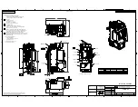
Page 37: ...RIX Industries 040910 01 Page 28 FIGURE 1 COMPRESSOR CROSS SECTION FASTENER DETAIL ...
Page 38: ...RIX Industries 040910 01 Page 29 FIGURE 2 COMPRESSOR CROSS SECTION PUMP DETAIL ...
Page 39: ...RIX Industries 040910 01 Page 30 FIGURE 3 1ST STAGE VALVE DETAIL ...
Page 40: ...RIX Industries 040910 01 Page 31 FIGURE 4 2ND STAGE VALVE DETAIL ...
Page 41: ...RIX Industries 040910 01 Page 32 FIGURE 5 EXTERIOR FASTENER DETAIL ...
Page 42: ...RIX Industries 040910 01 Page 33 FIGURE 6 MOTOR AND CONTROL BOX MOUNTING ...
Page 43: ...RIX Industries 040910 01 Page 34 FIGURE 7 SUCTION PLUMBING DETAIL ...
Page 44: ...RIX Industries 040910 01 Page 35 FIGURE 8 INTERSTAGE PLUMBING DETAIL ...
Page 45: ...RIX Industries 040910 01 Page 36 FIGURE 9 FINAL DISCHARGE PLUMBING DETAIL ...
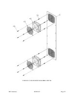
Page 46: ...RIX Industries 040910 01 Page 37 FIGURE 10 COOLING FAN SUB ASSEMBLY DETAIL ...
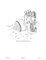
Page 47: ...RIX Industries 040910 01 Page 38 FIGURE 11 BELT INSTALLATION DETAIL ...
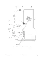
Page 48: ...RIX Industries 040910 01 Page 39 FIGURE 12 GUARD MOUNTING DETAIL ...
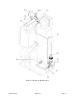
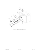
Page 49: ...RIX Industries 040910 01 Page 40 FIGURE 13 CONTROL BOX DETAIL 1 OF 2 ...
Page 50: ...RIX Industries 040910 01 Page 41 FIGURE 14 CONTROL BOX DETAIL 2 OF 2 ...
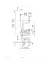
Page 51: ...RIX Industries 040910 01 Page 42 FIGURE 15 CONTROL BOX WIRING DIAGRAM ...
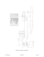
Page 52: ...RIX Industries 040910 01 Page 43 FIGURE 16 ELECTRICAL SCHEMATIC ...
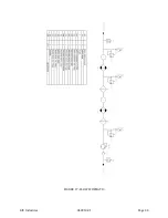
Page 53: ...RIX Industries 040910 01 Page 44 FIGURE 17 FLOW SCHEMATIC ...
Page 57: ......
Page 58: ......

