RIX Industries
040910-01
Page v
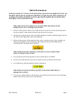
Safety Precautions
Safety precautions are necessary for the protection of personnel and equipment. Prior to any
attempt to install, operate, maintain, troubleshoot, or repair any part of the compressor, all
warnings and cautions included here and/or appearing throughout this manual should be
thoroughly reviewed and understood.
DANGER
This symbol means if the danger is not avoided, it will cause death, serious
bodily injury, or severe damage to the machine.
1.
Before working on the compressor, all internal pressure must be relieved, and compressor
must be isolated or disconnected from all external pressure sources.
2.
All electrical components associated with this equipment shall be installed and grounded in
accordance with applicable codes and regulations.
3.
Before working on electrical equipment, take steps to ensure system is de-energized and
will remain so while work is in progress. All circuits not known to be DEAD must be
considered LIVE and dangerous at all times.
WARNING
This symbol means if the warning is not heeded, it can cause death, bodily
injury, or damage to the machine.
4.
Do not operate unit if safety guards are removed, damaged, or modified.
5.
Do not reset relief valves for any pressure higher than as specified in this manual.
6.
Do not make any unauthorized alteration to equipment.
CAUTION
This symbol means if precaution is not taken, it may cause bodily injury or
damage to the machine.
7.
Do not touch cylinder heads or discharge gas lines from the heads up to the heat exchanger
inlets. These are hot and can cause serious burns.
Summary of Contents for 2PS-15-115
Page 37: ...RIX Industries 040910 01 Page 28 FIGURE 1 COMPRESSOR CROSS SECTION FASTENER DETAIL ...
Page 38: ...RIX Industries 040910 01 Page 29 FIGURE 2 COMPRESSOR CROSS SECTION PUMP DETAIL ...
Page 39: ...RIX Industries 040910 01 Page 30 FIGURE 3 1ST STAGE VALVE DETAIL ...
Page 40: ...RIX Industries 040910 01 Page 31 FIGURE 4 2ND STAGE VALVE DETAIL ...
Page 41: ...RIX Industries 040910 01 Page 32 FIGURE 5 EXTERIOR FASTENER DETAIL ...
Page 42: ...RIX Industries 040910 01 Page 33 FIGURE 6 MOTOR AND CONTROL BOX MOUNTING ...
Page 43: ...RIX Industries 040910 01 Page 34 FIGURE 7 SUCTION PLUMBING DETAIL ...
Page 44: ...RIX Industries 040910 01 Page 35 FIGURE 8 INTERSTAGE PLUMBING DETAIL ...
Page 45: ...RIX Industries 040910 01 Page 36 FIGURE 9 FINAL DISCHARGE PLUMBING DETAIL ...
Page 46: ...RIX Industries 040910 01 Page 37 FIGURE 10 COOLING FAN SUB ASSEMBLY DETAIL ...
Page 47: ...RIX Industries 040910 01 Page 38 FIGURE 11 BELT INSTALLATION DETAIL ...
Page 48: ...RIX Industries 040910 01 Page 39 FIGURE 12 GUARD MOUNTING DETAIL ...
Page 49: ...RIX Industries 040910 01 Page 40 FIGURE 13 CONTROL BOX DETAIL 1 OF 2 ...
Page 50: ...RIX Industries 040910 01 Page 41 FIGURE 14 CONTROL BOX DETAIL 2 OF 2 ...
Page 51: ...RIX Industries 040910 01 Page 42 FIGURE 15 CONTROL BOX WIRING DIAGRAM ...
Page 52: ...RIX Industries 040910 01 Page 43 FIGURE 16 ELECTRICAL SCHEMATIC ...
Page 53: ...RIX Industries 040910 01 Page 44 FIGURE 17 FLOW SCHEMATIC ...
Page 57: ......
Page 58: ......

