RIX Industries
040910-01
Page 7
Chapter 4 - Control System
4.1
System Overview
This unit has an integrated control box wired for auto stop/start capability. Pressure switches
prevent the unit from operating outside of design ranges if discharge pressure rises too high or
suction pressure falls too low. The unit is also equipped with an hour meter to log cumulative run
time.
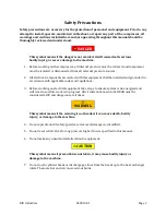
WARNING
The control box contains
high voltage
. Before working on electrical equipment,
take steps to ensure the system is de-energized and will remain so while work is in
progress. All circuits not known to be dead must be considered live and dangerous
at all times.
Suction pressure must be supplied to compressor before startup to keep the rod loading and/or
compression ratios within limits. Ideally the pressure in the discharge plumbing should be bled
down to the level of the suction pressure before startup. User should include provisions to allow an
unloaded start up when connecting to the compressor.
The control system is designed for two modes of operation:
1.
Manual start / automatic stop
2.
Auto start / stop based on both suction and discharge pressure
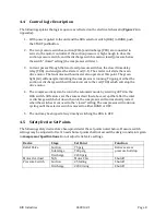
A HOA (Hand/Off/Auto) switch is located on the front of the control box and allows operator choice
of modes. A remote contact is installed in the control box and can tied into to an ancillary control
system for remote start/stop, signal line use, etc. If such control is desired, remove pink jumper
wired between contact blocks 1 and 3 in the control box.
4.2
Manual Operation Mode
With the selector switch in the HAND position, the compressor is in manual mode and will start
when the START pushbutton is pressed. The unit will continue to run until one of the safety
switches stops the unit. At that point the compressor will not restart until the START pushbutton is
pressed again. If any switch remains past its trip setting the compressor will not start. To manually
stop the unit, switch the HOA switch to the OFF position.
4.3
Auto Operation Mode
With the selector switch in the AUTO position the compressor will automatically start and stop
based on the signals from both the suction and discharge pressure switches. When shutdown by
either switch, the compressor will remain on standby until the pressure reverts back to the "closed"
point of the switch at which point the compressor will restart. To manually stop the unit, switch the
HOA switch to the OFF position.
Summary of Contents for 2PS-15-115
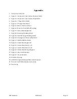
Page 37: ...RIX Industries 040910 01 Page 28 FIGURE 1 COMPRESSOR CROSS SECTION FASTENER DETAIL ...
Page 38: ...RIX Industries 040910 01 Page 29 FIGURE 2 COMPRESSOR CROSS SECTION PUMP DETAIL ...
Page 39: ...RIX Industries 040910 01 Page 30 FIGURE 3 1ST STAGE VALVE DETAIL ...
Page 40: ...RIX Industries 040910 01 Page 31 FIGURE 4 2ND STAGE VALVE DETAIL ...
Page 41: ...RIX Industries 040910 01 Page 32 FIGURE 5 EXTERIOR FASTENER DETAIL ...
Page 42: ...RIX Industries 040910 01 Page 33 FIGURE 6 MOTOR AND CONTROL BOX MOUNTING ...
Page 43: ...RIX Industries 040910 01 Page 34 FIGURE 7 SUCTION PLUMBING DETAIL ...
Page 44: ...RIX Industries 040910 01 Page 35 FIGURE 8 INTERSTAGE PLUMBING DETAIL ...
Page 45: ...RIX Industries 040910 01 Page 36 FIGURE 9 FINAL DISCHARGE PLUMBING DETAIL ...
Page 46: ...RIX Industries 040910 01 Page 37 FIGURE 10 COOLING FAN SUB ASSEMBLY DETAIL ...
Page 47: ...RIX Industries 040910 01 Page 38 FIGURE 11 BELT INSTALLATION DETAIL ...
Page 48: ...RIX Industries 040910 01 Page 39 FIGURE 12 GUARD MOUNTING DETAIL ...
Page 49: ...RIX Industries 040910 01 Page 40 FIGURE 13 CONTROL BOX DETAIL 1 OF 2 ...
Page 50: ...RIX Industries 040910 01 Page 41 FIGURE 14 CONTROL BOX DETAIL 2 OF 2 ...
Page 51: ...RIX Industries 040910 01 Page 42 FIGURE 15 CONTROL BOX WIRING DIAGRAM ...
Page 52: ...RIX Industries 040910 01 Page 43 FIGURE 16 ELECTRICAL SCHEMATIC ...
Page 53: ...RIX Industries 040910 01 Page 44 FIGURE 17 FLOW SCHEMATIC ...
Page 57: ......
Page 58: ......

