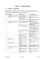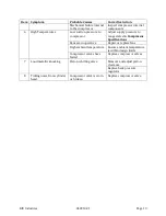
RIX Industries
040910-01
Page 9
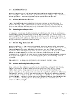
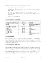
Chapter 5 - Routine Inspection & Scheduled Maintenance
5.1
Introduction
The purpose of this chapter is to provide the operator with the routine inspection and scheduled
maintenance information required to ensure a long service life of the subject compressor. RIX
recommends documenting and tracking service history using the
Service Log
in the appendix of
this manual.
5.2
Routine Inspection
1.
Visually inspect the system for obvious damage or leakage. Fix any issues that are found.
2.
Check pressures and temperatures against normal operation.
3.
Check cooling air flow. Verify cooling fans blow air over the heads.
4.
Inspect for loose fittings or components. Fix any issues that are found.
5.
Inspect for unusual noises or vibrations.
5.3
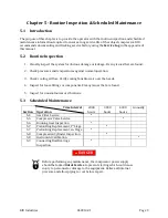
Scheduled Maintenance
Section
Time Interval
Operation
2000
hours
3000
hours
4000
hours
Annually
5.4
Gas Filter Service
*
5.5
Compressor Valve Service
*
5.6
Running Gear Inspection
*
5.7
Piston Ring Replacement, 1
st
Stage
*
5.7
Piston Ring Replacement, 2
nd
Stage
*
5.8
Compression Cylinder Inspection
*
5.8
Instrument Calibration
*
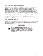
5.9
Connecting Rod Bearings
Inspection
*
DANGER
Before performing any maintenance, the compressor power supply
should be locked
Out of Service
to prevent starting which could cause
injury to personnel or damage to the equipment. Relieve all internal
pressure and allow piping to cool before repair.
Summary of Contents for 2PS-15-115
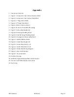
Page 37: ...RIX Industries 040910 01 Page 28 FIGURE 1 COMPRESSOR CROSS SECTION FASTENER DETAIL ...
Page 38: ...RIX Industries 040910 01 Page 29 FIGURE 2 COMPRESSOR CROSS SECTION PUMP DETAIL ...
Page 39: ...RIX Industries 040910 01 Page 30 FIGURE 3 1ST STAGE VALVE DETAIL ...
Page 40: ...RIX Industries 040910 01 Page 31 FIGURE 4 2ND STAGE VALVE DETAIL ...
Page 41: ...RIX Industries 040910 01 Page 32 FIGURE 5 EXTERIOR FASTENER DETAIL ...
Page 42: ...RIX Industries 040910 01 Page 33 FIGURE 6 MOTOR AND CONTROL BOX MOUNTING ...
Page 43: ...RIX Industries 040910 01 Page 34 FIGURE 7 SUCTION PLUMBING DETAIL ...
Page 44: ...RIX Industries 040910 01 Page 35 FIGURE 8 INTERSTAGE PLUMBING DETAIL ...
Page 45: ...RIX Industries 040910 01 Page 36 FIGURE 9 FINAL DISCHARGE PLUMBING DETAIL ...
Page 46: ...RIX Industries 040910 01 Page 37 FIGURE 10 COOLING FAN SUB ASSEMBLY DETAIL ...
Page 47: ...RIX Industries 040910 01 Page 38 FIGURE 11 BELT INSTALLATION DETAIL ...
Page 48: ...RIX Industries 040910 01 Page 39 FIGURE 12 GUARD MOUNTING DETAIL ...
Page 49: ...RIX Industries 040910 01 Page 40 FIGURE 13 CONTROL BOX DETAIL 1 OF 2 ...
Page 50: ...RIX Industries 040910 01 Page 41 FIGURE 14 CONTROL BOX DETAIL 2 OF 2 ...
Page 51: ...RIX Industries 040910 01 Page 42 FIGURE 15 CONTROL BOX WIRING DIAGRAM ...
Page 52: ...RIX Industries 040910 01 Page 43 FIGURE 16 ELECTRICAL SCHEMATIC ...
Page 53: ...RIX Industries 040910 01 Page 44 FIGURE 17 FLOW SCHEMATIC ...
Page 57: ......
Page 58: ......

