RIX Industries
040910-01
Page 15
3.
Install nuts in a cross pattern. Torque to 180 in-lbs.
4.
Verify that head is on square.
5.
Reconnect all plumbing to head.
7.4
Compressor Valves
A leaking valve, either suction or discharge, will usually be indicated by a loss in flow along with
low discharge pressure. This valve leakage is usually caused by wear, breakage, warping of the
reeds, or fouling due to particulates which prevent the valve from fully closing. Severe leakage will
cause over-heating of the suction pipe just prior to the cylinder head.
When valves are removed, they should be inspected for damage and/or wear. Inspect the reeds for
wear, cracking, or warping. Examine valve seat for wear or damage. A uniform imprint of the reed
indicates the valve is sealing normally, while radial lines or streaks extending outward indicate
leakage. Clean or replace parts as required. Valve seats may be reconditioned on a lapping plate
using a fine lapping compound or 600 grit sandpaper, moving in a figure 8 motion over the
sandpaper until it has a mirror finish.
To remove and disassemble both the 1
st
and 2
nd
stage compressor valves follow the instructions
below:
1.
Remove the head per
Section 7.3
and move to a flat, clean surface.
2.
Separate all components and discard the used O-rings. Note: a soft punch may be used to aid
with disassembly by removing the plug at the top of head and pushing through the now
open port.
To reinstall the 1
st
stage compressor valve, reference
Figure 3
and follow the instructions below:
1.
Install the discharge reed and O-ring in the 1
st
stage head valve pocket.
2.
Install the valve seat into the 1
st
stage head valve pocket, pushing down squarely to engage
the O-ring properly.
3.
Install the suction reed and final O-ring in the 1
st
stage head valve pocket.
4.
Install the head per
Section 7.3.
To reinstall the 2
nd
stage compressor valve, reference
Figure 4
and follow the instructions below:
1.
Install the valve spacer and locating pin in the 2
nd
stage head valve pocket.
2.
Install the discharge reed into the 1
st
stage head valve pocket, aligned with the pin. Ensure
the free end of the reed flap will sit over the 4 round, through holes on the valve seat.
Installing the reed upside down will result in improper valve operation.
3.
Install O-ring in the 2
nd
stage head valve pocket.
Summary of Contents for 2PS-15-115
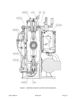
Page 37: ...RIX Industries 040910 01 Page 28 FIGURE 1 COMPRESSOR CROSS SECTION FASTENER DETAIL ...
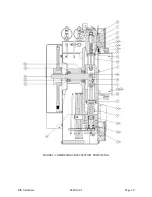
Page 38: ...RIX Industries 040910 01 Page 29 FIGURE 2 COMPRESSOR CROSS SECTION PUMP DETAIL ...
Page 39: ...RIX Industries 040910 01 Page 30 FIGURE 3 1ST STAGE VALVE DETAIL ...
Page 40: ...RIX Industries 040910 01 Page 31 FIGURE 4 2ND STAGE VALVE DETAIL ...
Page 41: ...RIX Industries 040910 01 Page 32 FIGURE 5 EXTERIOR FASTENER DETAIL ...
Page 42: ...RIX Industries 040910 01 Page 33 FIGURE 6 MOTOR AND CONTROL BOX MOUNTING ...
Page 43: ...RIX Industries 040910 01 Page 34 FIGURE 7 SUCTION PLUMBING DETAIL ...
Page 44: ...RIX Industries 040910 01 Page 35 FIGURE 8 INTERSTAGE PLUMBING DETAIL ...
Page 45: ...RIX Industries 040910 01 Page 36 FIGURE 9 FINAL DISCHARGE PLUMBING DETAIL ...
Page 46: ...RIX Industries 040910 01 Page 37 FIGURE 10 COOLING FAN SUB ASSEMBLY DETAIL ...
Page 47: ...RIX Industries 040910 01 Page 38 FIGURE 11 BELT INSTALLATION DETAIL ...
Page 48: ...RIX Industries 040910 01 Page 39 FIGURE 12 GUARD MOUNTING DETAIL ...
Page 49: ...RIX Industries 040910 01 Page 40 FIGURE 13 CONTROL BOX DETAIL 1 OF 2 ...
Page 50: ...RIX Industries 040910 01 Page 41 FIGURE 14 CONTROL BOX DETAIL 2 OF 2 ...
Page 51: ...RIX Industries 040910 01 Page 42 FIGURE 15 CONTROL BOX WIRING DIAGRAM ...
Page 52: ...RIX Industries 040910 01 Page 43 FIGURE 16 ELECTRICAL SCHEMATIC ...
Page 53: ...RIX Industries 040910 01 Page 44 FIGURE 17 FLOW SCHEMATIC ...
Page 57: ......
Page 58: ......

