RIX Industries
040910-01
Page vi
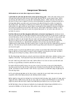
Oxygen Compatibility Requirements
DANGER
To prevent
FIRE, SERIOUS INJURY or DEATH
, it is the User’s
responsibility to ensure that all oxygen wetted parts used in the
compressor are cleaned for oxygen service prior to installation.
Oxygen compression equipment has very stringent requirements due to the hazards inherent in the
compression process. Cleaning and handling must be in accordance with Compressed Gas
Association
publication
CGA G-4.1
, Cleaning Equipment for Oxygen Service.
Any
work to be done on the compressor where the gas stream may be exposed must be done in
accordance with CGA procedures. RIX recommends that all maintenance be performed by qualified
personnel with full knowledge of oxygen equipment handling procedures and the potential hazards
of contamination. RIX further recommends returning the compressor package to RIX Industries or
RIX-approved service center when servicing or repairing this compressor package.
All gas plumbing and storage systems connected to the compressor must be oxygen clean,
constructed of oxygen compatible materials, and designed to safely handle the operating and design
pressures as defined in the registration page of this manual. Use only oxygen compatible O-ring
grease, such as RIX P/N 45-1007, and either Viton or Teflon O-rings in gas piping areas.
Factory cleaned oxygen parts are denoted by an “X” prefix at the beginning of the part number. It is
the User’s responsibility to maintain the cleanliness of factory cleaned parts and any existing
portions of the gas stream that may be exposed during installation or maintenance.
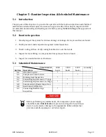
After any maintenance in which the gas stream of the unit becomes exposed, User should perform an
O2 burn-in, see
Section 3.2.
During this time personnel should be separated from the compressor.
Summary of Contents for 2PS-15-115
Page 37: ...RIX Industries 040910 01 Page 28 FIGURE 1 COMPRESSOR CROSS SECTION FASTENER DETAIL ...
Page 38: ...RIX Industries 040910 01 Page 29 FIGURE 2 COMPRESSOR CROSS SECTION PUMP DETAIL ...
Page 39: ...RIX Industries 040910 01 Page 30 FIGURE 3 1ST STAGE VALVE DETAIL ...
Page 40: ...RIX Industries 040910 01 Page 31 FIGURE 4 2ND STAGE VALVE DETAIL ...
Page 41: ...RIX Industries 040910 01 Page 32 FIGURE 5 EXTERIOR FASTENER DETAIL ...
Page 42: ...RIX Industries 040910 01 Page 33 FIGURE 6 MOTOR AND CONTROL BOX MOUNTING ...
Page 43: ...RIX Industries 040910 01 Page 34 FIGURE 7 SUCTION PLUMBING DETAIL ...
Page 44: ...RIX Industries 040910 01 Page 35 FIGURE 8 INTERSTAGE PLUMBING DETAIL ...
Page 45: ...RIX Industries 040910 01 Page 36 FIGURE 9 FINAL DISCHARGE PLUMBING DETAIL ...
Page 46: ...RIX Industries 040910 01 Page 37 FIGURE 10 COOLING FAN SUB ASSEMBLY DETAIL ...
Page 47: ...RIX Industries 040910 01 Page 38 FIGURE 11 BELT INSTALLATION DETAIL ...
Page 48: ...RIX Industries 040910 01 Page 39 FIGURE 12 GUARD MOUNTING DETAIL ...
Page 49: ...RIX Industries 040910 01 Page 40 FIGURE 13 CONTROL BOX DETAIL 1 OF 2 ...
Page 50: ...RIX Industries 040910 01 Page 41 FIGURE 14 CONTROL BOX DETAIL 2 OF 2 ...
Page 51: ...RIX Industries 040910 01 Page 42 FIGURE 15 CONTROL BOX WIRING DIAGRAM ...
Page 52: ...RIX Industries 040910 01 Page 43 FIGURE 16 ELECTRICAL SCHEMATIC ...
Page 53: ...RIX Industries 040910 01 Page 44 FIGURE 17 FLOW SCHEMATIC ...
Page 57: ......
Page 58: ......

