RIX
Industries
MAN
‐
2V3B
‐
4.1V
‐
P1
Page
10
5.7
PRESSURE
RELIEF
VALVES
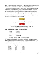
The pressure relief valves should be removed from the compressor, inspected for cleanliness, and
tested for correct set-point every 8000 hours or once per year. If a valve fails to lift at its rated
pressure, it must be readjusted, and if necessary, rebuilt or replaced.
5.8
GAS
PIPING
LEAK
CHECK
Every 1000 hours all piping joints should be examined for leaks. Leak testing requires that the
compressor be pressurized, and therefore running or recently run. Also check joints after reassembly
from maintenance.
A soapy solution in a squirt bottle works best for locating leaks in a gas system. Any gaskets and O-
rings needed for the repair should be on hand prior to attempting to fix a leak. This test is simplified
if the compressor is allowed to cool, then restarted immediately prior to running the leak test, since
the hot discharge pipes can boil away the soap solution making detection of leaks difficult or
impossible.
Caution
Do not use any flammable solution for leak testing.
Warning
Hot discharge lines can produce painful burns - be careful to avoid
making contact with hot pipes. Wear safety glasses at all times.
PROCEDURE:
a.
Restart compressor after it has been allowed to cool down.
b.
Systematically move from joint to joint and fitting to fitting in the gas system piping,
spraying the leak test solution.
c.
Observe for the formation of bubbles. Mark location of any detected leaks. Large leaks
may blow the soap solution away as quickly as it is applied. These may be detected by
feel, again being careful of hot discharge lines.
d.
O-ring joints cannot be corrected by additional tightening. In most cases, a new o-ring
must be installed. Always inspect the surfaces that seal against the o-ring for defects
and correct as required. Insure the proper durometer (hardness) o-ring is used.
Note: See Drawing A5089 for O-ring installation and material information
5.9
VALVES
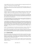
Valves should be inspected every 4000 hours of operation, or earlier if pressures vary from normal,
flow capacity drops, noise is detected or an abnormally high temperature is observed. The customer
Summary of Contents for 2V3B-4.1V-P1A
Page 46: ...RIX Industries MAN 2V3B 4 1V P1 Page 37 FIGURE 1 GENERAL COMPRESSOR DETAIL 1 4 ...
Page 47: ...RIX Industries MAN 2V3B 4 1V P1 Page 38 FIGURE 2 GENERAL COMPRESSOR DETAIL 2 4 ...
Page 48: ...RIX Industries MAN 2V3B 4 1V P1 Page 39 FIGURE 3 GENERAL COMPRESSOR DETAIL 3 4 ...
Page 49: ...RIX Industries MAN 2V3B 4 1V P1 Page 40 FIGURE 4 COMPRESSION VALVE DETAIL ...
Page 50: ...RIX Industries MAN 2V3B 4 1V P1 Page 41 FIGURE 5 GENERAL COMPRESSOR DETAIL 4 4 ...
Page 51: ...RIX Industries MAN 2V3B 4 1V P1 Page 42 FIGURE 6 FIRST STAGE COMPRESSION STAGE DETAIL ...
Page 53: ...RIX Industries MAN 2V3B 4 1V P1 Page 44 FIGURE 8 SUCTION AND FIRST STAGE PLUMBING DETAIL ...
Page 54: ...RIX Industries MAN 2V3B 4 1V P1 Page 45 FIGURE 9 SECOND AND THIRD STAGE PLUMBING DETAIL ...
Page 55: ...RIX Industries MAN 2V3B 4 1V P1 Page 46 FIGURE 10 FINAL DISCHARGE PLUMBING DETAIL ...
Page 56: ...RIX Industries MAN 2V3B 4 1V P1 Page 47 FIGURE 11 CRANKCASE ASSEMBLY DETAIL ...
Page 57: ...RIX Industries MAN 2V3B 4 1V P1 Page 48 FIGURE 12 CONNECTING ROD DETAIL ...
Page 58: ...RIX Industries MAN 2V3B 4 1V P1 Page 49 FIGURE 13 CONTROL BOX ASSEMBLY DETAIL 1 3 ...
Page 59: ...RIX Industries MAN 2V3B 4 1V P1 Page 50 FIGURE 14 CONTROL BOX ASSEMBLY DETAIL 2 3 ...
Page 60: ...RIX Industries MAN 2V3B 4 1V P1 Page 51 FIGURE 15 CONTROL BOX ASSEMBLY DETAIL 3 3 ...
Page 61: ...RIX Industries MAN 2V3B 4 1V P1 Page 52 FIGURE 16 WIRING SCHEMATIC ...
Page 62: ...RIX Industries MAN 2V3B 4 1V P1 Page 53 FIGURE 17 ELECTRICAL SCHEMATIC ...
Page 65: ...RIX Industries MAN 2V3B 4 1V P1 Page 55 FIGURE 18 FLOW SCHEMATIC ...
Page 70: ...RIX P N 76 713 X76 713 DWG A8042 CUI SP CTI PROPIN ...
Page 71: ...RIX P N 76 713 X76 713 DWG A8042 CUI SP CTI PROPIN ...
Page 77: ......
Page 78: ......
Page 79: ......
Page 80: ......
Page 81: ... ǣ ...
Page 82: ... Ǥ ǣ ...

