RIX
Industries
MAN
‐
2V3B
‐
4.1V
‐
P1
Page
24
Incorrect Orientation Correct Orientation
j.
Reinstall the guide cylinders over the guide pistons.
k.
Fill crankcase with new oil.
l.
Reinstall the compression cylinder assemblies per instructions.
m.
Install distance piece covers.
7.12
MAIN
BEARINGS
The crankshaft is supported in the crankcase by two main bearings. They are a tapered roller design.
Lubrication is supplied by crankcase oil splash. There is no scheduled maintenance for the main
bearings.
REMOVE
MAIN
BEARINGS
.
a.
The compressor must be completely disassembled. See applicable
instructions.
b.
Remove the flywheel and bushing by removing the three cap screws that
secure the flywheel and bushing to the crankshaft. Use these screws in the
bushing tapped holes to jack the flywheel and bushing apart. This will
"unlock" the bushing from the crankshaft.
c.
Remove the bearing support cover and connecting rods. NOTE: There are
notches in the bearing support cover gasket so that the gasket is not damaged
during disassembly.
d.
Pull the crankshaft forward and remove it from the crankcase.
e.
With a suitable puller, remove the bearings from each end of the crankshaft.
INSTALL
MAIN
BEARINGS
.
a.
Thoroughly clean the crankcase,
crankshaft and bearing cover.
b.
Press a new bearing on each end of the crankshaft main bearing journals.
Preheating the bearings to 250
˚
F will facilitate installation.
c.
Install a new shaft seal in the crankcase.
d.
Install the crankshaft with bearings into the crankcase.
Summary of Contents for 2V3B-4.1V-P1A
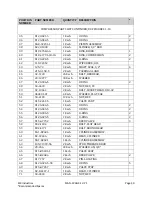
Page 46: ...RIX Industries MAN 2V3B 4 1V P1 Page 37 FIGURE 1 GENERAL COMPRESSOR DETAIL 1 4 ...
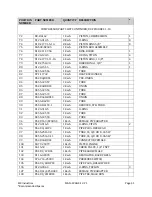
Page 47: ...RIX Industries MAN 2V3B 4 1V P1 Page 38 FIGURE 2 GENERAL COMPRESSOR DETAIL 2 4 ...
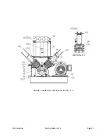
Page 48: ...RIX Industries MAN 2V3B 4 1V P1 Page 39 FIGURE 3 GENERAL COMPRESSOR DETAIL 3 4 ...
Page 49: ...RIX Industries MAN 2V3B 4 1V P1 Page 40 FIGURE 4 COMPRESSION VALVE DETAIL ...
Page 50: ...RIX Industries MAN 2V3B 4 1V P1 Page 41 FIGURE 5 GENERAL COMPRESSOR DETAIL 4 4 ...
Page 51: ...RIX Industries MAN 2V3B 4 1V P1 Page 42 FIGURE 6 FIRST STAGE COMPRESSION STAGE DETAIL ...
Page 53: ...RIX Industries MAN 2V3B 4 1V P1 Page 44 FIGURE 8 SUCTION AND FIRST STAGE PLUMBING DETAIL ...
Page 54: ...RIX Industries MAN 2V3B 4 1V P1 Page 45 FIGURE 9 SECOND AND THIRD STAGE PLUMBING DETAIL ...
Page 55: ...RIX Industries MAN 2V3B 4 1V P1 Page 46 FIGURE 10 FINAL DISCHARGE PLUMBING DETAIL ...
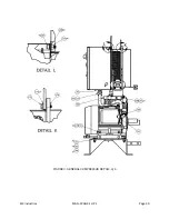
Page 56: ...RIX Industries MAN 2V3B 4 1V P1 Page 47 FIGURE 11 CRANKCASE ASSEMBLY DETAIL ...
Page 57: ...RIX Industries MAN 2V3B 4 1V P1 Page 48 FIGURE 12 CONNECTING ROD DETAIL ...
Page 58: ...RIX Industries MAN 2V3B 4 1V P1 Page 49 FIGURE 13 CONTROL BOX ASSEMBLY DETAIL 1 3 ...
Page 59: ...RIX Industries MAN 2V3B 4 1V P1 Page 50 FIGURE 14 CONTROL BOX ASSEMBLY DETAIL 2 3 ...
Page 60: ...RIX Industries MAN 2V3B 4 1V P1 Page 51 FIGURE 15 CONTROL BOX ASSEMBLY DETAIL 3 3 ...
Page 61: ...RIX Industries MAN 2V3B 4 1V P1 Page 52 FIGURE 16 WIRING SCHEMATIC ...
Page 62: ...RIX Industries MAN 2V3B 4 1V P1 Page 53 FIGURE 17 ELECTRICAL SCHEMATIC ...
Page 65: ...RIX Industries MAN 2V3B 4 1V P1 Page 55 FIGURE 18 FLOW SCHEMATIC ...
Page 70: ...RIX P N 76 713 X76 713 DWG A8042 CUI SP CTI PROPIN ...
Page 71: ...RIX P N 76 713 X76 713 DWG A8042 CUI SP CTI PROPIN ...
Page 77: ......
Page 78: ......
Page 79: ......
Page 80: ......
Page 81: ... ǣ ...
Page 82: ... Ǥ ǣ ...


