RIX
Industries
MAN
‐
2V3B
‐
4.1V
‐
P1
Page
v
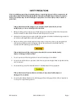
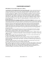
SAFETY
PRECAUTIONS
Prior
to
installing,
operating,
troubleshooting,
or
repairing
any
part
of
this
compressor,
all
precautions
stated
in
this
manual
should
be
reviewed
and
understood.
Failure
to
observe
safety
precautions
may
result
in
damage
to
equipment
or
serious
injury
and/or
death
to
personnel.
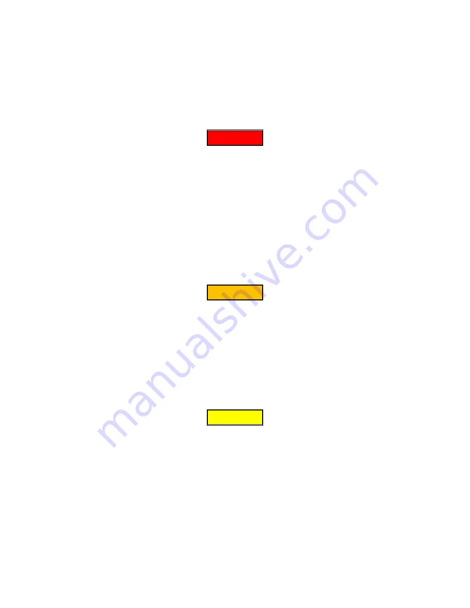
Danger
This
symbol
means
if
the
danger
is
not
avoided,
it
will
cause
death,
serious
bodily
injury,
or
severe
damage
to
the
machine.
1.
Before working on the compressor, all internal pressure must be relieved and compressor
must be isolated or disconnected from all external pressure sources.
2.
All electrical components associated with this equipment shall be installed and grounded in
accordance with applicable codes and regulations.
3.
Before working on electrical equipment, take steps to ensure system is de-energized and
will remain so while work is in progress. All circuits not known to be DEAD must be
considered LIVE and dangerous at all times.
Warning
This
symbol
means
if
the
warning
is
not
heeded,
it
can
cause
death,
bodily
injury,
or
damage
to
the
machine.
1.
Do not operate unit if safety guards are removed, damaged, or modified.
2.
Do not reset relief valves or pressure switch for any pressure higher than as specified in the
service manual.
3.
Do not make any unauthorized alteration or modifications to the equipment.
Caution
This
symbol
means
if
precaution
is
not
taken,
it
may
cause
bodily
injury
or
damage
to
the
machine.
4.
Do not touch cylinder heads or the discharge gas lines during operation. Allow compressor
to cool prior to preforming service.
Summary of Contents for 2V3B-4.1V-P1A
Page 46: ...RIX Industries MAN 2V3B 4 1V P1 Page 37 FIGURE 1 GENERAL COMPRESSOR DETAIL 1 4 ...
Page 47: ...RIX Industries MAN 2V3B 4 1V P1 Page 38 FIGURE 2 GENERAL COMPRESSOR DETAIL 2 4 ...
Page 48: ...RIX Industries MAN 2V3B 4 1V P1 Page 39 FIGURE 3 GENERAL COMPRESSOR DETAIL 3 4 ...
Page 49: ...RIX Industries MAN 2V3B 4 1V P1 Page 40 FIGURE 4 COMPRESSION VALVE DETAIL ...
Page 50: ...RIX Industries MAN 2V3B 4 1V P1 Page 41 FIGURE 5 GENERAL COMPRESSOR DETAIL 4 4 ...
Page 51: ...RIX Industries MAN 2V3B 4 1V P1 Page 42 FIGURE 6 FIRST STAGE COMPRESSION STAGE DETAIL ...
Page 53: ...RIX Industries MAN 2V3B 4 1V P1 Page 44 FIGURE 8 SUCTION AND FIRST STAGE PLUMBING DETAIL ...
Page 54: ...RIX Industries MAN 2V3B 4 1V P1 Page 45 FIGURE 9 SECOND AND THIRD STAGE PLUMBING DETAIL ...
Page 55: ...RIX Industries MAN 2V3B 4 1V P1 Page 46 FIGURE 10 FINAL DISCHARGE PLUMBING DETAIL ...
Page 56: ...RIX Industries MAN 2V3B 4 1V P1 Page 47 FIGURE 11 CRANKCASE ASSEMBLY DETAIL ...
Page 57: ...RIX Industries MAN 2V3B 4 1V P1 Page 48 FIGURE 12 CONNECTING ROD DETAIL ...
Page 58: ...RIX Industries MAN 2V3B 4 1V P1 Page 49 FIGURE 13 CONTROL BOX ASSEMBLY DETAIL 1 3 ...
Page 59: ...RIX Industries MAN 2V3B 4 1V P1 Page 50 FIGURE 14 CONTROL BOX ASSEMBLY DETAIL 2 3 ...
Page 60: ...RIX Industries MAN 2V3B 4 1V P1 Page 51 FIGURE 15 CONTROL BOX ASSEMBLY DETAIL 3 3 ...
Page 61: ...RIX Industries MAN 2V3B 4 1V P1 Page 52 FIGURE 16 WIRING SCHEMATIC ...
Page 62: ...RIX Industries MAN 2V3B 4 1V P1 Page 53 FIGURE 17 ELECTRICAL SCHEMATIC ...
Page 65: ...RIX Industries MAN 2V3B 4 1V P1 Page 55 FIGURE 18 FLOW SCHEMATIC ...
Page 70: ...RIX P N 76 713 X76 713 DWG A8042 CUI SP CTI PROPIN ...
Page 71: ...RIX P N 76 713 X76 713 DWG A8042 CUI SP CTI PROPIN ...
Page 77: ......
Page 78: ......
Page 79: ......
Page 80: ......
Page 81: ... ǣ ...
Page 82: ... Ǥ ǣ ...


