Rev 2-17
A5089K
O-RING INSTALLATION & MATERIAL INFORMATION
All RIX part numbers for o-rings begin with a 123 prefix. This is followed by a second set
of 3 digits which corresponds to US Standard
AS568
sizing.
RIX normally uses a
Viton
70 durometer
o-ring, in which case the part number will have a
“-5” suffix, such as 123-040-5. In many cases a
90 durometer
is used, which is indicated
by an additional “-90” at the end of the part number, such as
123-040-5-90.
Viton is
required for oxygen or high temperature service, and 90 durometer is often required in high
temp/ high pressure locations. For materials other than Viton a different suffix is used (see
chart below).
CAUTION:
All o-rings
used in
O2 service
must be
Viton or Teflon
. Buna o-rings are not
oxygen compatible and will sustain combustion, creating a high potential for explosion.
All o-rings, except for those located behind piston rings, should be lubricated with an
appropriate high temperature grease such as
Krytox
or
Christo-Lube
MGC-111
before
installation. Apply a thin coating by drawing the o-ring through your fingers. This will
extend the life of the seal and simplify installation.
CAUTION:
O-rings used in oxygen service must be lubed with an
oxygen compatible
grease (RIX P/N 45-1007, 45-19220 or equivalent).
All o-rings supplied for
O2
service
have an
X prefix
, and are oxygen cleaned and bagged to
maintain cleanliness. Never use a non-O2
cleaned part for oxygen service.
Standard o-rings available from hardware stores, etc. are usually Buna type and will fail
when used in high temperature or oxygen applications.
O-RING & BACK-UP RING MATERIALS
RIX PART NO.
MATERIAL
O-rings
123-XXX-2, -2S
Silicone
123-XXX-3
Teflon
123-XXX-5
Viton
123-XXX-7
Kel-F
123-XXX-9
Kal-Rez, Compound 2037
123-XXX-10
Viton with FDA approval
123-XXX-11
Viton V1289-75, Low temp (-50°F)
123-XXX-12
Parafluor Ultra, FF102-75
X123-XXX-5
Viton (
O
XYGEN
C
LEANED
)
Back-up Rings
124-XXX-3
Teflon (split)
124-XXX-8
Teflon (solid)
Note:
Some –7 o-rings are metal and some –9's are metallic C-rings. But these
P/N's take the form 123-XXXX-7 and –9 (
FOUR
X'
S
)
Summary of Contents for 2V3B-4.1V-P1A
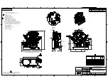
Page 46: ...RIX Industries MAN 2V3B 4 1V P1 Page 37 FIGURE 1 GENERAL COMPRESSOR DETAIL 1 4 ...
Page 47: ...RIX Industries MAN 2V3B 4 1V P1 Page 38 FIGURE 2 GENERAL COMPRESSOR DETAIL 2 4 ...
Page 48: ...RIX Industries MAN 2V3B 4 1V P1 Page 39 FIGURE 3 GENERAL COMPRESSOR DETAIL 3 4 ...
Page 49: ...RIX Industries MAN 2V3B 4 1V P1 Page 40 FIGURE 4 COMPRESSION VALVE DETAIL ...
Page 50: ...RIX Industries MAN 2V3B 4 1V P1 Page 41 FIGURE 5 GENERAL COMPRESSOR DETAIL 4 4 ...
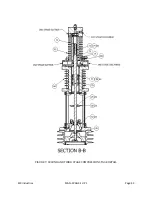
Page 51: ...RIX Industries MAN 2V3B 4 1V P1 Page 42 FIGURE 6 FIRST STAGE COMPRESSION STAGE DETAIL ...
Page 53: ...RIX Industries MAN 2V3B 4 1V P1 Page 44 FIGURE 8 SUCTION AND FIRST STAGE PLUMBING DETAIL ...
Page 54: ...RIX Industries MAN 2V3B 4 1V P1 Page 45 FIGURE 9 SECOND AND THIRD STAGE PLUMBING DETAIL ...
Page 55: ...RIX Industries MAN 2V3B 4 1V P1 Page 46 FIGURE 10 FINAL DISCHARGE PLUMBING DETAIL ...
Page 56: ...RIX Industries MAN 2V3B 4 1V P1 Page 47 FIGURE 11 CRANKCASE ASSEMBLY DETAIL ...
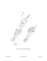
Page 57: ...RIX Industries MAN 2V3B 4 1V P1 Page 48 FIGURE 12 CONNECTING ROD DETAIL ...
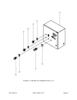
Page 58: ...RIX Industries MAN 2V3B 4 1V P1 Page 49 FIGURE 13 CONTROL BOX ASSEMBLY DETAIL 1 3 ...
Page 59: ...RIX Industries MAN 2V3B 4 1V P1 Page 50 FIGURE 14 CONTROL BOX ASSEMBLY DETAIL 2 3 ...
Page 60: ...RIX Industries MAN 2V3B 4 1V P1 Page 51 FIGURE 15 CONTROL BOX ASSEMBLY DETAIL 3 3 ...
Page 61: ...RIX Industries MAN 2V3B 4 1V P1 Page 52 FIGURE 16 WIRING SCHEMATIC ...
Page 62: ...RIX Industries MAN 2V3B 4 1V P1 Page 53 FIGURE 17 ELECTRICAL SCHEMATIC ...
Page 65: ...RIX Industries MAN 2V3B 4 1V P1 Page 55 FIGURE 18 FLOW SCHEMATIC ...
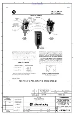
Page 70: ...RIX P N 76 713 X76 713 DWG A8042 CUI SP CTI PROPIN ...
Page 71: ...RIX P N 76 713 X76 713 DWG A8042 CUI SP CTI PROPIN ...
Page 77: ......
Page 78: ......
Page 79: ......
Page 80: ......
Page 81: ... ǣ ...
Page 82: ... Ǥ ǣ ...

