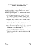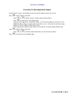
For setting on rise, apply desired pressure and turn adjustment left until switch actu-
ates (circuit across N.O. and COM terminals closes). For setting on fall, apply pressure
equal to normal system operating pressure. Reduce source pressure to setpoint
value. Turn adjustment right until switch actuates (circuit across N.C. and COM closes).
5. After completing adjustments, slide cover closed over adjustment compartment.
Recheck set point.
CP110825K
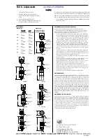
Tools Needed
Screwdriver
1.
Connect control to pressure source.
2.
With power disconnected, slide cover toward
electrical terminations while twisting it to overcome
friction.
3.
Connect power to terminals or leads.
4.
Insert screwdriver into adjustment slot and turn left
to increase setting or right to decrease setting.
Part II - Adjustments
Dimensions
Dimension A
Diaphragm
Piston
Model
10-12
Model
13-16
10-A 3”
3.31”
76.2 mm
84.1 mm
10-B 3.5”
3.81”
88.9 mm
96.8 mm
10-C 4.06”
4.38”
103.2 mm
111.1 mm
10-D 3.19”
3.5”
81.0 mm
88.9 mm
10-E 3.9”
4.25”
100 mm
108 mm
10-F 4.13”
4.44”
104.8 mm
112.7 mm
10-G 3.88”
4.19”
98.4 mm
106.4 mm
RECOMMENDED PRACTICES AND WARNINGS
United Electric Controls Company recommends careful consideration
of the following factors when specifying and installing UE pressure and temper-
ature units. Before installing a unit, the Installation and Maintenance instruc-
tions provided with unit must be read and understood.
6Q CXQKF FCOCIKPI WPKV RTQQH RTGUUWTG CPF OCZKOWO VGORGTCVWTG NKOKVU
UVCVGFKPNKVGTCVWTGCPFQPPCOGRNCVGUOWUVPGXGTDGGZEGGFGFGXGPD[UWTI
-
GUKPVJGU[UVGO1RGTCVKQPQHVJGWPKVWRVQOCZKOWORTGUUWTGQTVGORGTC
-
ture is acceptable on a limited basis (e.g., start-up, testing) but continuous
QRGTCVKQP OWUV DG TGUVTKEVGF VQ VJG FGUKIPCVGF CFLWUVCDNG TCPIG 'ZEGUUKXG
E[ENKPICVOCZKOWORTGUUWTGQTVGORGTCVWTGNKOKVUEQWNFTGFWEGUGPUQTNKHG
# DCEMWR WPKV KU PGEGUUCT[ HQT CRRNKECVKQPU YJGTG FCOCIG VQ C RTKOCT[
WPKVEQWNFGPFCPIGTNKHGNKODQTRTQRGTV[#JKIJQTNQYNKOKVUYKVEJKUPGE
-
essary for applications where a dangerous runaway condition could result.
6JG CFLWUVCDNG TCPIG OWUV DG UGNGEVGF UQ VJCV KPEQTTGEV KPCFXGTVGPV QT
malicious setting at any range point cannot result in an unsafe system
condition.
+PUVCNN WPKV YJGTG UJQEM XKDTCVKQP CPF CODKGPV VGORGTCVWTG HNWEVWCVKQPU
will not damage unit or affect operation. Orient unit so that moisture does
not enter the enclosure via the electrical connection. When appropriate, this
entry point should be sealed to prevent moisture entry.
7PKVOWUVPQVDGCNVGTGFQTOQFKHKGFCHVGTUJKROGPV%QPUWNV7'KHOQFKHK
-
cation is necessary.
/QPKVQT QRGTCVKQP VQ QDUGTXG YCTPKPI UKIPU QH RQUUKDNG FCOCIG VQ WPKV
UWEJCUFTKHVKPUGVRQKPVQTHCWNV[FKURNC[%JGEMWPKVKOOGFKCVGN[
2TGXGPVCVKXG OCKPVGPCPEG CPF RGTKQFKE VGUVKPI KU PGEGUUCT[ HQT ETKVKECN
applications where damage could endanger property or personnel.
(QTCNNCRRNKECVKQPUCHCEVQT[UGVWPKVUJQWNFDGVGUVGFDGHQTGWUG
'NGEVTKECN TCVKPIU UVCVGF KP NKVGTCVWTG CPF QP PCOGRNCVG OWUV PQV DG
GZEGGFGF1XGTNQCFQPCUYKVEJECPECWUGFCOCIGGXGPQPVJGHKTUVE[ENG
Wire unit according to local and national electrical codes, using wire size
recommended in installation sheet.
&QPQVOQWPVWPKVKPCODKGPVVGORGZEGGFKPIRWDNKUJGFNKOKVU
LIMITED WARRANTY
Seller warrants that the product hereby purchased is, upon delivery, free from
FGHGEVUKPOCVGTKCNCPFYQTMOCPUJKRCPFVJCVCP[UWEJRTQFWEVYJKEJKUHQWPF
VQDGFGHGEVKXGKPUWEJYQTMOCPUJKRQTOCVGTKCNYKNNDGTGRCKTGFQTTGRNCEGFD[
5GNNGT 'ZYQTMU (CEVQT[ 9CVGTVQYP /CUUCEJ0%16'4/5 RTQXKFGF
however, that this warranty applies only to equipment found to be so defective
within a period of 24 months from the date of manufacture by the Seller. Seller
UJCNN PQV DG QDNKICVGF WPFGT VJKU YCTTCPV[ HQT CNNGIGF FGHGEVU YJKEJ GZCOKPC
-
tion discloses are due to tampering, misuse, neglect, improper storage, and in
any case where products are disassembled by anyone other than authorized
5GNNGT¶U TGRTGUGPVCVKXGU ':%'26 (14 6*' .+/+6'& 9#44#06; 1( 4'2#+4
#0& 4'2.#%'/'06 56#6'& #$18' 5'..'4 &+5%.#+/5 #.. 9#44#06+'5
9*#651'8'4 9+6* 4'52'%6 61 6*' 241&7%6 +0%.7&+0) #.. +/2.+'&
9#44#06+'5 1( /'4%*#06#$+.+6 ; 14 (+60'55 (14 #0; 2#46+%7.#4
274215'
LIMITATION OF SELLER’S LIABILITY
Seller’s liability to Buyer for any loss or claim, including liability incurred in
EQPPGEVKQP YKVJ K DTGCEJ QH CP[ YCTTCPV[ YJCVUQGXGT GZRTGUUGF QT KORNKGF
(ii) a breach of contract, (iii) a negligent act or acts (or negligent failure to
act) committed by Seller, or (iv) an act for which strict liability will be inputted
to seller, is limited to the “limited warranty” of repair and/or replacement as
so stated in our warranty of product. In no event shall the Seller be liable for
CP[ URGEKCN KPFKTGEV EQPUGSWGPVKCN QT QVJGT FCOCIGU QH C NKMG IGPGTCN PCVWTG
KPENWFKPIYKVJQWVNKOKVCVKQPNQUUQHRTQHKVUQTRTQFWEVKQPQTNQUUQTGZRGPUGUQH
any nature incurred by the buyer or any third party.
UE specifications subject to change without notice.
Dimension B
Model 10-12: 1/8 NPT
Model 13-16: 1/4 NPT
Type 10-A
“A”
“B”
Type 10-C
“A”
Type 10-D
“A”
“B”
Type 10-G
“A”
“B”
Type 10-F
“A”
“B”
180 Dexter Avenue, P.O. Box 9143
Watertown, MA 02471-9143 USA
Telephone: 617 926-1000 Fax: 617 926-2568
http://www.ueonline.com
U N I T E D E L E C T R I C
C O N T R O L S
IM10-07
“A”
“B”
Type 10-E
Type 10-B
“A”
“B”
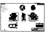
A8101 PRESSURE SWITCH SPEC SHEET RIX P/N X76-714, 76-715, 76-716, X76-735
CUI//SP-CTI/PROPIN
Summary of Contents for 2V3B-4.1V-P1A
Page 46: ...RIX Industries MAN 2V3B 4 1V P1 Page 37 FIGURE 1 GENERAL COMPRESSOR DETAIL 1 4 ...
Page 47: ...RIX Industries MAN 2V3B 4 1V P1 Page 38 FIGURE 2 GENERAL COMPRESSOR DETAIL 2 4 ...
Page 48: ...RIX Industries MAN 2V3B 4 1V P1 Page 39 FIGURE 3 GENERAL COMPRESSOR DETAIL 3 4 ...
Page 49: ...RIX Industries MAN 2V3B 4 1V P1 Page 40 FIGURE 4 COMPRESSION VALVE DETAIL ...
Page 50: ...RIX Industries MAN 2V3B 4 1V P1 Page 41 FIGURE 5 GENERAL COMPRESSOR DETAIL 4 4 ...
Page 51: ...RIX Industries MAN 2V3B 4 1V P1 Page 42 FIGURE 6 FIRST STAGE COMPRESSION STAGE DETAIL ...
Page 53: ...RIX Industries MAN 2V3B 4 1V P1 Page 44 FIGURE 8 SUCTION AND FIRST STAGE PLUMBING DETAIL ...
Page 54: ...RIX Industries MAN 2V3B 4 1V P1 Page 45 FIGURE 9 SECOND AND THIRD STAGE PLUMBING DETAIL ...
Page 55: ...RIX Industries MAN 2V3B 4 1V P1 Page 46 FIGURE 10 FINAL DISCHARGE PLUMBING DETAIL ...
Page 56: ...RIX Industries MAN 2V3B 4 1V P1 Page 47 FIGURE 11 CRANKCASE ASSEMBLY DETAIL ...
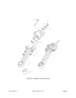
Page 57: ...RIX Industries MAN 2V3B 4 1V P1 Page 48 FIGURE 12 CONNECTING ROD DETAIL ...
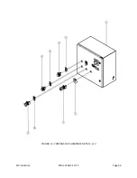
Page 58: ...RIX Industries MAN 2V3B 4 1V P1 Page 49 FIGURE 13 CONTROL BOX ASSEMBLY DETAIL 1 3 ...
Page 59: ...RIX Industries MAN 2V3B 4 1V P1 Page 50 FIGURE 14 CONTROL BOX ASSEMBLY DETAIL 2 3 ...
Page 60: ...RIX Industries MAN 2V3B 4 1V P1 Page 51 FIGURE 15 CONTROL BOX ASSEMBLY DETAIL 3 3 ...
Page 61: ...RIX Industries MAN 2V3B 4 1V P1 Page 52 FIGURE 16 WIRING SCHEMATIC ...
Page 62: ...RIX Industries MAN 2V3B 4 1V P1 Page 53 FIGURE 17 ELECTRICAL SCHEMATIC ...
Page 65: ...RIX Industries MAN 2V3B 4 1V P1 Page 55 FIGURE 18 FLOW SCHEMATIC ...
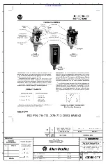
Page 70: ...RIX P N 76 713 X76 713 DWG A8042 CUI SP CTI PROPIN ...
Page 71: ...RIX P N 76 713 X76 713 DWG A8042 CUI SP CTI PROPIN ...
Page 77: ......
Page 78: ......
Page 79: ......
Page 80: ......
Page 81: ... ǣ ...
Page 82: ... Ǥ ǣ ...


