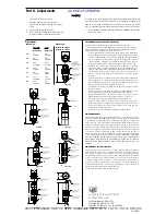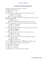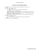
Controller Set up & Set point Adjustment
-Power up and wait until the ambient temperature is displayed.
-Hold
until
is displayed.
-Release
button.
-Press
2 times to display INPT. This parameter is for adjusting input sensor type.
-Press
one time to display Pt.dn.
-Press
once to return to INPT display.
-Press
once todisplayUNIT. This parameter is for adjusting units of measurement. The 2V3
generally displays in Degrees F.
-Press
once to display°F
-Press
once to return to UNIT (Units can be changed to Celsius if desired).
-Press
once to display dP. This parameter is for adjusting the amount of decimal digits.
-Press
once to display No dP.
-Press
once to return to dP.
-Press
six times to display Pb. This parameter is for adjusting the proportional band value.
-Press
until 0.0 is displayed.
-Press
to return to Pb.
-Press
once to display out1. This parameter is for adjusting Output 1 function.
-Press
twice to display dirt.
-Press
once to return to out1.
-Press
once to return to o1.ty. This parameter is for adjusting Output 1 signal type.
-Press
to display RELY.
-Press
once to return to o1.ty
-Press and hold
until CAL1 is displayed.-Press
two times until SP1 is displayed.
-Press and hold
until desired set point is displayed. Default is 400.
-Press and hold
until Set is displayed.
-Press
one time to display Lock.
-Press
four times to display ALL.
-Press
for ten seconds. Ambient temperature will be displayed.
A11346 PAGE 4 OF 5
CUI//SP-CTI/PROPIN
Summary of Contents for 2V3B-4.1V-P1A
Page 46: ...RIX Industries MAN 2V3B 4 1V P1 Page 37 FIGURE 1 GENERAL COMPRESSOR DETAIL 1 4 ...
Page 47: ...RIX Industries MAN 2V3B 4 1V P1 Page 38 FIGURE 2 GENERAL COMPRESSOR DETAIL 2 4 ...
Page 48: ...RIX Industries MAN 2V3B 4 1V P1 Page 39 FIGURE 3 GENERAL COMPRESSOR DETAIL 3 4 ...
Page 49: ...RIX Industries MAN 2V3B 4 1V P1 Page 40 FIGURE 4 COMPRESSION VALVE DETAIL ...
Page 50: ...RIX Industries MAN 2V3B 4 1V P1 Page 41 FIGURE 5 GENERAL COMPRESSOR DETAIL 4 4 ...
Page 51: ...RIX Industries MAN 2V3B 4 1V P1 Page 42 FIGURE 6 FIRST STAGE COMPRESSION STAGE DETAIL ...
Page 53: ...RIX Industries MAN 2V3B 4 1V P1 Page 44 FIGURE 8 SUCTION AND FIRST STAGE PLUMBING DETAIL ...
Page 54: ...RIX Industries MAN 2V3B 4 1V P1 Page 45 FIGURE 9 SECOND AND THIRD STAGE PLUMBING DETAIL ...
Page 55: ...RIX Industries MAN 2V3B 4 1V P1 Page 46 FIGURE 10 FINAL DISCHARGE PLUMBING DETAIL ...
Page 56: ...RIX Industries MAN 2V3B 4 1V P1 Page 47 FIGURE 11 CRANKCASE ASSEMBLY DETAIL ...
Page 57: ...RIX Industries MAN 2V3B 4 1V P1 Page 48 FIGURE 12 CONNECTING ROD DETAIL ...
Page 58: ...RIX Industries MAN 2V3B 4 1V P1 Page 49 FIGURE 13 CONTROL BOX ASSEMBLY DETAIL 1 3 ...
Page 59: ...RIX Industries MAN 2V3B 4 1V P1 Page 50 FIGURE 14 CONTROL BOX ASSEMBLY DETAIL 2 3 ...
Page 60: ...RIX Industries MAN 2V3B 4 1V P1 Page 51 FIGURE 15 CONTROL BOX ASSEMBLY DETAIL 3 3 ...
Page 61: ...RIX Industries MAN 2V3B 4 1V P1 Page 52 FIGURE 16 WIRING SCHEMATIC ...
Page 62: ...RIX Industries MAN 2V3B 4 1V P1 Page 53 FIGURE 17 ELECTRICAL SCHEMATIC ...
Page 65: ...RIX Industries MAN 2V3B 4 1V P1 Page 55 FIGURE 18 FLOW SCHEMATIC ...
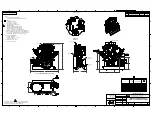
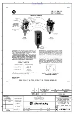
Page 70: ...RIX P N 76 713 X76 713 DWG A8042 CUI SP CTI PROPIN ...
Page 71: ...RIX P N 76 713 X76 713 DWG A8042 CUI SP CTI PROPIN ...
Page 77: ......
Page 78: ......
Page 79: ......
Page 80: ......
Page 81: ... ǣ ...
Page 82: ... Ǥ ǣ ...


