background image

Summary of Contents for 2V3B-4.1V-P1A

Page 1: ...4 1V P1A P1B P1C P1E RIX Industries 3 Stage Oil Free Air Cooled Oxygen Compressor This manual including information and products referenced herein to be provided by Seller Products are subject to U S export control laws and will not be resold re exported or retransferred directly or indirectly to any person in violation of U S Export Administration Regulations ...

Page 2: ...Maintenance Section 5 2 C 03 14 18 AM 28 Guide cylinder nut torque reduced to 19 ft lbs D 02 03 20 SF 29 30 Removed valve assembly XAO15 A5759 1 Updated items 1 2 19 20 E 04 22 20 AM ICB i vi 31 ECN 17822 Formatting Changes F 06 16 21 ICB Appendix ECO 010722 Parts List Update G 11 15 21 AV Title Page viii 1 36 54 ECO 011491 H 12 6 21 AV Appendix ECO 011546 I 02 16 22 AV Appendix New Rev of Interfa...

Page 3: ...1 SYSTEM CHECKOUT 4 3 3 START UP 4 3 4 NORMAL OPERATING PRESSURE RANGES 5 3 5 RELIEF VALVE SETTINGS 5 CHAPTER 4 CONTROL SYSTEM AND UNLOADED STARTUP 6 4 1 SAFETY SWITCH SETTINGS 6 4 2 CONTROL SYSTEM 6 CHAPTER 5 ROUTINE INSPECTION AND SCHEDULED MAINTENANCE 8 5 1 ROUTINE INSPECTION 8 5 2 SCHEDULED MAINTENANCE 9 5 3 FILTER 9 5 4 CRANKCASE LUBRICATING OIL 9 5 5 MOTOR LUBRICATION 9 5 6 DRIVE BELTS 9 5 7...

Page 4: ...D PISTON 1ST STAGE 19 7 6 2 REPLACE PISTON RING FIXED PISTON 2ND STAGE 19 7 6 3 REPLACE PISTON RING FLOATING PISTON 3RD STAGE 20 7 7 PISTON RODS OIL WIPER SEALS 21 7 7 1 INSTALL PISTON ROD AND OIL SEALS 21 7 8 PISTON ROD ADJUSTMENT 21 7 9 CRANKSHAFT SHAFT SEAL 22 7 10 GUIDE CYLINDERS 22 7 11 CONNECTING RODS 23 7 12 MAIN BEARINGS 24 CHAPTER 8 CLEARANCES TOLERANCES 26 CHAPTER 9 SPECIFIED TORQUES 27 ...

Page 5: ... or procure them in advance as lead times and availability can vary RIX also offers service and overhaul kits to support other scheduled maintenance requirements COMPRESSOR IDENTIFICATION Please record the information indicated below to provide in communication with RIX about parts service warranty claims or any other information related to this compressor Compressor Model Type 2V3B 4 1V Location ...

Page 6: ...talled and grounded in accordance with applicable codes and regulations 3 Before working on electrical equipment take steps to ensure system is de energized and will remain so while work is in progress All circuits not known to be DEAD must be considered LIVE and dangerous at all times Warning This symbol means if the warning is not heeded it can cause death bodily injury or damage to the machine ...

Page 7: ...ards of contamination RIX further recommends returning the compressor package to RIX Industries or RIX approved service center when servicing or repairing this compressor package All gas plumbing and storage systems connected to the compressor must be oxygen clean constructed of oxygen compatible materials and designed to safely handle the operating and design pressures as defined in the registrat...

Page 8: ...tiation Seller shall at its option either repair or replace its part at the original F O B point of delivery Defective items must be held for Seller s inspection and returned to the original F O B point upon request C With respect to parts not manufactured or services not performed by Seller Seller assigns to Buyer whatever warranty Seller receives from the Supplier of such parts or services Howev...

Page 9: ...Input Design Gas Clean Dry Oxygen Pressure 30 to 40 PSIG Dew Point 40 F Maximum Gas Output Flow 10 6 SCFM at 40 PSIG 100 F inlet Pressure 2500 PSIG Maximum Design basis of SCFM is 70 F and 14 7 psia General Design Design Speed 540 RPM Compressor Design Three stage oil free compression air cooled Cylinder Sizes 2 1 4 1 3 8 5 8 Stroke Length 3 Electrical Requirements Drive Motor 10 HP Control Circui...

Page 10: ...SSION This compressor is designed to safely compress without cylinder oil lubrication Teflon based piston rings are used in all stages The compression cylinders are isolated from the crankcase lubricating oil by crosshead distance pieces and metal slingers on the piston rods 1 3 GAS FLOW Gas entering at the suction of the first stage is successively compressed through three stages to provide the f...

Page 11: ...low User s suction and discharge plumbing should be designed to accommodate compressor vibration CAUTION If flexible lines are used user is responsible to secure those lines to prevent whipping in case of breakage Safety relief valves are installed on the compressor at each stage of compression suction interstage and discharge Do not start the compressor without these items properly installed All ...

Page 12: ...CTRICAL CONNECTIONS The unit must be wired to a source of power in accordance with applicable codes The compressor should be connected to power such that the cooling fan pulls air over the heat exchanger 2 5 STORAGE If the compressor is taken out of service provision should be made to protect against corrosion At a minimum gas suction and discharge lines should be capped The compressor should be r...

Page 13: ...pure oxygen This step should take at least 30 minutes This will allow any organic materials left in the system to safely oxidize 3 3 START UP Supply the required suction pressure to the compressor inlet Check for leaks in the system and correct as necessary Start the compressor and observe the pressure gauges The final pressure will increase quickly to the Back Pressure Regulator BPR setting The i...

Page 14: ...ature shutdown switch by manually lowering setting while operating at full pressure SEE CHAPTER 4 FOR CONTROL SYSTEM INFORMATION Warning A painful burn can be caused by touching any of the cylinder heads or discharge gas lines from the heads to the inter aftercooler Danger Do not stick hand inside distance piece when unit is running Metal slingers on piston rods will crush fingers 3 4 NORMAL OPERA...

Page 15: ...itch is adjustable See instructions in appendix for adjustments In the event of an emergency an E Stop button is provided The E Stop will disconnect all power to the control box The E Stop has a mechanical Push Pull latch Pushing the button will stop all operation To continue operation pull the E Stop button to reengage circuit control Warning If the unit is in AUTO mode when the E Stop button is ...

Page 16: ...and energizes the starter coil KM The starter coil starts the main drive motor M The fan motor FM and hour meter HM also operate at this point The green light HL1 will energize indicating the compressor is running Tripping of either the inlet or discharge switch will break current to the coil which will stop the drive motor d If the 3rd stage temperature reaches the switch set point the temperatur...

Page 17: ...tems connected to the compressor must be oxygen clean and constructed of oxygen compatible materials No attempt should be made to work on the machine without full knowledge of oxygen equipment handling procedures and the potential hazards of contamination Cleaning should be in accordance with Compressed Gas Association publication CGA G 4 1 Cleaning Equipment for Oxygen Service www cganet com Any ...

Page 18: ...e injury to personnel or damage to the equipment Allow piping to cool before repair 5 3 FILTER Every 3000 hours or as required the discharge filter should be cleaned or replaced 5 4 CRANKCASE LUBRICATING OIL Every 3000 hours of running time or annually the crankcase oil should be renewed Failing to change the oil as scheduled may result in premature or accelerated wear to the running gear cranksha...

Page 19: ...fficult or impossible Caution Do not use any flammable solution for leak testing Warning Hot discharge lines can produce painful burns be careful to avoid making contact with hot pipes Wear safety glasses at all times PROCEDURE a Restart compressor after it has been allowed to cool down b Systematically move from joint to joint and fitting to fitting in the gas system piping spraying the leak test...

Page 20: ...tage piston ring blowby passes into the 2nd stage compression area As the 3rd stage rings wear the 2nd stage pressure will tend to increase Too much ring blowby will cause the 2nd stage relief valve to pop at which point the 3rd stage rings must be replaced If the 2nd stage rings are also worn excessively their leak rate may prevent the 2nd stage pressure from increasing Gas leaking past either th...

Page 21: ... 12 PISTON ROD OIL SEALS The oil seals prevent crankcase oil from leaking into the distance piece area If leakage occurs remove and clean piston rod and replace seals If scratches are found on rod surface refinish per instructions in chapter 7 ...

Page 22: ...ted inlet filter or suction piping f Low suction pressure to compressor NOTE Operating compressor with a low inter stage pressure may cause overheating of the final stage resulting in premature ring wear High inter stage pressures will be caused by one or more of the following a Leaking valves on the next stage b Worn piston rings on 3rd stage NOTE Leaking valves in any stage can cause a slight wa...

Page 23: ...hing The pulleys have a hub that can be separated by removing the three bolts and using them as jacking devices by inserting into the threaded holes in the hub and tightening sequentially until the pulley breaks free When loose the pulley and hub can be slid back and forth on the shaft to achieve alignment To align use a straight edge across the outside faces of the pulleys The gap between the str...

Page 24: ...ge will usually be indicated by a higher than normal pressure on the preceding stage or in the case of the first stage a loss in flow along with low inter stage pressures This can be caused by wear breakage or fouling due to particulates in the valves which prevent them from fully closing Remove and service the valves every 4500 hours of operation or if any of the inter stage pressures vary from n...

Page 25: ...ring the small hole in the valve seat d Set the suction reed on the valve seat using a small amount of compatible O ring grease which will hold the reed in place when the head is installed on the cylinder If a new reed is used bend the tab to a 45 degree angle into the slot provided in the valve seat Do not put grease on or near the valve finger Note a 2nd o ring can be installed to assist in hold...

Page 26: ...SSEMBLY VALVE REMOVAL a Remove gas inlet and discharge lines from head Remove the plug from the center top of head Remove the two nuts Lift off head b Remove the first o ring Be careful not to scratch the inside surface of the head Remove the suction valve stop and suction valve Remove pin from valve seat being careful not to bend Remove the second o ring c Remove the valve seat from the head usin...

Page 27: ...w into discharge port No air should pass if valve and seat are correctly installed d Install the second o ring second pin and the suction reed Be careful to orient the reed correctly with the seat e Install the valve stop and the third o ring f Reinstall the head and tighten in 5 ft lb increments to 15 ft lbs lubed threads Caution The nuts holding the head in place must be removed and installed us...

Page 28: ...d each new ring and install in groove making sure the ends of the ring fit completely into the groove f Compress each ring by hand and work the piston into the bore Rotating piston may be helpful Slide piston back and forth in the bore several times then remove and check to ensure all rings are fully seated in the ring grooves and have not pulled out and over side of the piston If necessary the la...

Page 29: ...t 1 4 6 mm of the piston ring can be cut off g Reinstall the 2nd stage head per valve assembly instructions Section 7 4 2 h Reinstall cylinder assembly onto compressor i Adjust piston rod height per 7 8 j Rotate the flywheel by hand several times to be certain that the parts are free Piston ring break in None required 7 6 3 REPLACE PISTON RING FLOATING PISTON 3RD STAGE Note See drawing in the back...

Page 30: ... startup Inspect o ring on oil wiper box and replace if necessary b Install o ring slinger onto piston rod Slide oil packing box onto rod and then attach piston rod jam nut with machined side down c Screw the rod into the guide piston until the threads bottom d Reinstall the cylinder assemblies and adjust piston rod per instructions below Caution The piston to cylinder head clearance adjustment is...

Page 31: ... and the crankshaft removed prior to seal removal c Inspect the crankshaft surface where the oil seal makes contact Remove any burrs or scratches that might inhibit a tight seal Be careful to avoid getting any foreign material on the exposed bearing REASSEMBLY a Reassemble in the reverse order using a new oil seal b Be sure that the flywheel and drive sheave are lined up This can be accomplished b...

Page 32: ...ce as required e Inspect the wrist pin and needle bearings for wear or damage replace if necessary When pressing needle bearings into the connecting rod be sure to press against the stamped end end with identification markings of bearings There are two needle bearings per rod and the end of each bearing should be flush with the outside of the connecting rod f Install the guide piston on a new rod ...

Page 33: ... three cap screws that secure the flywheel and bushing to the crankshaft Use these screws in the bushing tapped holes to jack the flywheel and bushing apart This will unlock the bushing from the crankshaft c Remove the bearing support cover and connecting rods NOTE There are notches in the bearing support cover gasket so that the gasket is not damaged during disassembly d Pull the crankshaft forwa...

Page 34: ...evel with proper oil g Install the flywheel hub and key drive V belts and beltguard in the reverse order of removal Insure that flywheel and driver sheave are lined up h Replace compression cylinder assemblies per instructions i Connect all other equipment in reverse order of disassembly j Turn the flywheel by hand a few revolutions to be certain everything is clear before starting the compressor ...

Page 35: ...ring Clearance 001 004 in Max Guide Cylinder 4 331 Dia Dia 002 in Max Guide Piston 4 325 Dia Dia 002 in Max Guide Piston to Cylinder Clearance 006 009 in Max Piston Rods 500 Dia 002 in wear Pistons 2 1 4 2 230 2 220 not a wearing part 1 3 8 1 370 1 368 003 diametrical wear 5 8 6235 623 001 diametrical wear Cylinders Bores 2 1 4 2 250 2 251 004 in diametrical wear 1 3 8 1 375 1 376 002 in diametric...

Page 36: ... Plate Nuts 30 2nd Stage Head Nuts 30 3rd Stage Head Nuts 15 Oil Wiper Box Gland Bolts 5 Oil Wiper Box Set Screw 1 2 Piston Rod Jam Nuts 25 Distance Piece Mounting Bolts 30 Guide Cylinder Nuts 19 Connecting Rod Nuts 15 Crankcase End Cover Bolts 30 Flywheel Bushing Bolts 40 Motor Sheave Hub Bolts SD bushing 1 4 20 9 Motor Sheave Hub Bolts SK bushing 5 16 18 15 _________________________ Dry Torque ...

Page 37: ...ase Assembly Detail 13 Figure 12 Connecting Rod Detail 14 Figure 13 Control Box Assembly Detail 1 3 15 Figure 14 Control Box Assembly Detail 2 3 16 Figure 15 Control Box Assembly Detail 3 3 17 Figure 16 Wiring Schematic 18 Figure 17 Electrical Schematic 19 Table 1 Wiring and Electrical Schematic Legend 20 Table 2 Control Box Transformer and Overload Setpoints 21 Figure 18 Flow Schematic 22 Interfa...

Page 38: ...LIEF VALVE 8 X515 792 1 Each RELIEF VALVE 9 X515 24662 1 Each RELIEF VALVE 10 X515 911 1 Each RELIEF VALVE 11 X60 865 1 Each PRESSURE GAUGE 12 53 4744 12 Each NUT LOCK 13 040327 01 12 Each SCREW FLAT HEAD PHILLIPS 14 20 6375 12 Each WASHER FLAT AN 6 15 X60 855 1 Each PRESSURE GAUGE 16 X60 24647 1 Each PRESSURE GAUGE 17 X60 853 1 Each PRESSURE GAUGE 18 X715 47 1 4 Each HAND VALVE 19 X54P 44FBUSS 5 ...

Page 39: ... 2 48 53 4409 2 Each NUT HEX SS 49 32 13664 2 Each BOLT SOCKET HEAD 10 32 50 040491 01 4 Each WASHER FLAT SAE 51 53 4103 12 Each NUT HEX 52 X15 C2445 1 Each VALVE PART 53 X123 044 5 1 Each O RING 2 54 X123 045 5 1 Each O RING 2 55 X123 035 5 1 Each O RING 2 56 X123 025 5 1 Each O RING 2 57 X15 A7792 3 Each REED VALVE 3 58 X32 1184 2 Each BOLT FLAT HEAD 59 X32 4171 4 Each BOLT ROUND HEAD 60 XA1 D26...

Page 40: ...X455 C2554 1 Each TUBE 87 X455 C2573 1 Each TUBE 88 X54P 64HBUSS 1 Each UNION 89 X455 B6210 1 Each TUBE 90 X554 B6199 1 1 Each REDUCER STR THRD 91 X123 910 5 1 Each O RING 92 X455 C2559 1 Each TUBE 93 X455 C2555 1 Each TUBE 94 X54P 163 4F5OGS 1 Each FEMALE PIPE ADAPTER 95 X123 916 5 1 Each O RING VITON 2 96 X54P 3 4HPS 1 Each PIPE PLUG HEX HEAD 97 X455 25160 9 1 Each TUBE SS 3 8 OD X 065 W 98 X455...

Page 41: ...2V 125 20 692 8 Each FLATWASHER 5 16 NOM 126 32 1162 4 Each BOLT HEX HEAD 127 53 77 4 Each NUT HEX 142 61 8251 1 375 Foot CONDUIT NONMETALLIC 143 138 8255 2 Each FITTING NONMET 1 2 45EL 144 54P 4P50NSS 1 Each PLUG ST THD HEX HEAD 145 A70 22975 1 Each BEDPLATE ASSY 2V3 146 A100 24523 1 Each CRANKCASE ASSEMBLY 147 16 A7937 2 Each GASKET 2 148 66 D2725 2 Each DISTANCE PIECE 2V3 149 40 D2713 1 Each BR...

Page 42: ... Each WASHER FLAT SAE 178 32 4529 3 Each BOLT HEX HEAD 179 32 13663 12 Each BOLT SOCKET HEAD 180 32 4577 2 Each BOLT HEX HEAD 182 105 C1993 54 4 Each STUD 17 4 SS 183 105 C1993 80 4 Each STUD THREADED ROD 184 20 23161 4 Each WASHER M4 ZINC PLATED 185 32 10321 4 Each BOLT HEX HEAD 186 107 26282 1 Each MOTOR 10 HP 215T TEFC 187 61 8252 3 Foot CONDUIT NONMET PVC 3 4 188 142 215T 1 Each SLIDE BASE MOT...

Page 43: ...TER BREATHER 4 16 B7036 1 EACH GASKET END COVER 1 5 181 1001 2 EACH BALL BEARING 6 5 C2760 1 EACH CRANKSHAFT 7 100 D2961 1 EACH CRANKCASE 8 53 4891 8 EACH NUT HEX 9 1 D2962 2 EACH CYLINDER GUIDE 10 16 B7037 2 EACH GASKET GUIDE CYL BASE 2 11 105 1028 8 EACH STUD THREADED ROD 12 125 1003 1 EACH SEAL SHAFT 1 13 60 1078 1 EACH GAUGE SIGHT LEVEL 14 20 12877 4 EACH WASHER 15 54 3076 1 EACH CAP 16 715 19...

Page 44: ...DICATOR LIGHT RED 5 158 B12708 05 1 EACH INDICATOR LIGHT GREEN 6 158 B12708 06 1 EACH BLACK BUTTON 1 N O CONTACT 7 158 B12708 07 1 EACH EMERGENCY STOP SWITCH RED 8 158 B12708 08 1 EACH 22MM BUTTON INDICATOR PLATE 9 158 B12708 09 1 EACH E STOP INDICATOR PLATE 10 158 B12708 10 1 EACH 3 POSITION SWITCH PLATE 11 158 B12708 11 1 EACH RED INDICATOR LIGHT PLATE 12 158 B12708 12 1 EACH SWITCH 3 POSITION S...

Page 45: ... EACH TERMINAL BLOCK 33 158 B12708 33 2 EACH 2 POSITION JUMPER 34 158 B12708 34 1 EACH 3 POSITION JUMPER Model Specific Parts MODEL NUMBER PART NUMBER QUANTITY MOTOR SHEAVE OPTION 2V3B 4 1V P1A 36 2B056 1 Each 2V3B 4 1V P1B 36 2B056 1 Each 2V3B 4 1V P1C 36 2B066 1 Each 2V3B 4 1V P1E 36 2B056 1 Each DRIVE BELT OPTION 2V3B 4 1V P1A 41 B75 1 2 Each 2V3B 4 1V P1B 41 B75 1 2 Each 2V3B 4 1V P1C 41 B76 1...

Page 46: ...RIX Industries MAN 2V3B 4 1V P1 Page 37 FIGURE 1 GENERAL COMPRESSOR DETAIL 1 4 ...

Page 47: ...RIX Industries MAN 2V3B 4 1V P1 Page 38 FIGURE 2 GENERAL COMPRESSOR DETAIL 2 4 ...

Page 48: ...RIX Industries MAN 2V3B 4 1V P1 Page 39 FIGURE 3 GENERAL COMPRESSOR DETAIL 3 4 ...

Page 49: ...RIX Industries MAN 2V3B 4 1V P1 Page 40 FIGURE 4 COMPRESSION VALVE DETAIL ...

Page 50: ...RIX Industries MAN 2V3B 4 1V P1 Page 41 FIGURE 5 GENERAL COMPRESSOR DETAIL 4 4 ...

Page 51: ...RIX Industries MAN 2V3B 4 1V P1 Page 42 FIGURE 6 FIRST STAGE COMPRESSION STAGE DETAIL ...

Page 52: ...RIX Industries MAN 2V3B 4 1V P1 Page 43 FIGURE 7 SECOND AND THIRD STAGE COMPRESSION STAGE DETAIL ...

Page 53: ...RIX Industries MAN 2V3B 4 1V P1 Page 44 FIGURE 8 SUCTION AND FIRST STAGE PLUMBING DETAIL ...

Page 54: ...RIX Industries MAN 2V3B 4 1V P1 Page 45 FIGURE 9 SECOND AND THIRD STAGE PLUMBING DETAIL ...

Page 55: ...RIX Industries MAN 2V3B 4 1V P1 Page 46 FIGURE 10 FINAL DISCHARGE PLUMBING DETAIL ...

Page 56: ...RIX Industries MAN 2V3B 4 1V P1 Page 47 FIGURE 11 CRANKCASE ASSEMBLY DETAIL ...

Page 57: ...RIX Industries MAN 2V3B 4 1V P1 Page 48 FIGURE 12 CONNECTING ROD DETAIL ...

Page 58: ...RIX Industries MAN 2V3B 4 1V P1 Page 49 FIGURE 13 CONTROL BOX ASSEMBLY DETAIL 1 3 ...

Page 59: ...RIX Industries MAN 2V3B 4 1V P1 Page 50 FIGURE 14 CONTROL BOX ASSEMBLY DETAIL 2 3 ...

Page 60: ...RIX Industries MAN 2V3B 4 1V P1 Page 51 FIGURE 15 CONTROL BOX ASSEMBLY DETAIL 3 3 ...

Page 61: ...RIX Industries MAN 2V3B 4 1V P1 Page 52 FIGURE 16 WIRING SCHEMATIC ...

Page 62: ...RIX Industries MAN 2V3B 4 1V P1 Page 53 FIGURE 17 ELECTRICAL SCHEMATIC ...

Page 63: ...T RED STOP 1 M ELECRIC MOTOR 1 SPD PRESS SWITCH DISCHARGE 1 SPI PRESS SWITCH INLET 1 KA RELAY 1 RTD RESISTIVE TEMPERATURE DEVICE 1 SB2 PUSH BUTTON START 1 TIS TEMPERATURE SWITCH 1 TC1 TRANSFORMER 500VA 1 SB1 PUSH PULL BUTTON EMERGENCY STOP 1 TABLE 2 CONTROL BOX TRANSFORMER AND OVERLOAD SETPOINTS MODEL PRIMARY TRANSFORMER SETTING SECONDARY TRANSFORMER SETTING MOTOR WIRING CONFIGURATION OVERLOAD SET...

Page 64: ... INPUT VOLTAGE MAX AMPS 2V3B 4 1V P1A O2 208 230V 3PH 60HZ 28A 2V3B 4 1V P1B O2 460V 3PH 60HZ 14A 2V3B 4 1V P1C O2 380 415V 3PH 50HZ 17A 2V3B 4 1V P1E O2 380 415V 3PH 60HZ 17A 2V3B 4 1V P1A N2 N2 208 230V 3PH 60HZ 28A 2V3B 4 1V P1B N2 N2 460V 3PH 60HZ 14A 2V3B 4 1V P1C N2 N2 380 415V 3PH 50HZ 17A 2V3B 4 1V P1E N2 N2 380 415V 3PH 60HZ 17A 2 6X 13 A B 16 31 3X 14 00 2X 14 00 2X 34 R 12X 1 00 6X LIFT...

Page 65: ...RIX Industries MAN 2V3B 4 1V P1 Page 55 FIGURE 18 FLOW SCHEMATIC ...

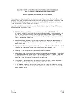
Page 66: ...gh temperature grease such as Krytox or Christo Lube MGC 111 before installation Apply a thin coating by drawing the o ring through your fingers This will extend the life of the seal and simplify installation CAUTION O rings used in oxygen service must be lubed with an oxygen compatible grease RIX P N 45 1007 45 19220 or equivalent All o rings supplied for O2 service have an X prefix and are oxyge...

Page 67: ...ng on sharp edge of the piston 2 Before stretching or uncoiling the spiral piston ring inspect the ring for cupping or damage If cupping is present the rings should be installed with the bottom of the dish down against the piston groove land 3 Gently stretch the piston ring and work it into the groove over the O ring Protect the thin ends of the piston ring with your thumb nail while working the r...

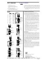
Page 68: ...ure carefully and thoroughly before starting Refer to the final page for the listing of Recommended Practices Liabilities and Warranties Part I Installation Optional Surface Mounting Bracket option M449 The surface mounting bracket is a C style clamp with a single clearance hole to accommodate a 1 4 screw Insert the unit into the bracket pressure connec tion end first Open the adjustment cover and...

Page 69: ...QFKHK cation is necessary QPKVQT QRGTCVKQP VQ QDUGTXG YCTPKPI UKIPU QH RQUUKDNG FCOCIG VQ WPKV UWEJ CU FTKHV KP UGV RQKPV QT HCWNV FKURNC JGEM WPKV KOOGFKCVGN 2TGXGPVCVKXG OCKPVGPCPEG CPF RGTKQFKE VGUVKPI KU PGEGUUCT HQT ETKVKECN applications where damage could endanger property or personnel QT CNN CRRNKECVKQPU C HCEVQT UGV WPKV UJQWNF DG VGUVGF DGHQTG WUG NGEVTKECN TCVKPIU UVCVGF KP NKVGTCVWTG CP...

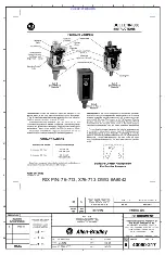
Page 70: ...RIX P N 76 713 X76 713 DWG A8042 CUI SP CTI PROPIN ...

Page 71: ...RIX P N 76 713 X76 713 DWG A8042 CUI SP CTI PROPIN ...

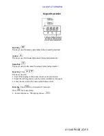
Page 72: ... Quick Guide Rix P N 76 12579 Drawing A11346 Rev B Table of Contents Description Page Keypad Operation 2 Unlock Screen 3 Controller Set up Set Point Adjustment 4 Procedure For Checking Switch Output 5 A11346 PAGE 1 OF 5 CUI SP CTI PROPIN ...

Page 73: ...ecrease the value of selected parameter Reset Key Press This key is used to 1 Revert the display to the process value or set point value 2 Reset the latching alarm once the alarm condition is removed 3 Enter the manual control menu when failure occurs Enter Key Press for a minimum of 5 seconds Press for 5 seconds to 1 Enter setup menu The display shows A11346 PAGE 2 OF 5 CUI SP CTI PROPIN ...

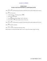
Page 74: ... 2 Release this button 3 Press again and it will display Lock on the screen 4 Press or until it displays none on the screen Press simultaneously and release the actual temperature will be displayed on the screen Press to see SP1 on display Press or to change the temperature setting Follow directions in document A11346 to lock the screen to prevent accidental change of settings A11346 PAGE 3 OF 5 C...

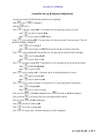
Page 75: ...e to display No dP Press once to return to dP Press six times to display Pb This parameter is for adjusting the proportional band value Press until 0 0 is displayed Press to return to Pb Press once to display out1 This parameter is for adjusting Output 1 function Press twice to display dirt Press once to return to out1 Press once to return to o1 ty This parameter is for adjusting Output 1 signal t...

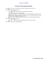
Page 76: ...tus Output 1 will close Verify continuity between terminals 5 and 6 WARNING When voltage is applied potential shock can occur Instead verify operation using a voltmeter Test for voltage on terminals 5 and 6 If the temperature controller is attached to the control box the red fault light will illuminate Press until the display shows SP1 Press or until the desired temperature set point has been reac...

Page 77: ......

Page 78: ......

Page 79: ......

Page 80: ......

Page 81: ... ǣ ...

Page 82: ... Ǥ ǣ ...

Reviews: