MAN-2V3B-4.1V REV (E)
25
7.11
CONNECTING RODS:
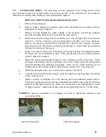
The connecting rod uses automotive type bearing inserts on the
large end and a pressed in needle bearing on the piston pin end. If the clearances are not within the
tolerances, the bearing shell, bushing or wrist pin should be replaced.
REPLACE
CONNECTING
RODS AND BEARING SETS
a.
Drain oil from crankcase.
b.
Remove heads, compression cylinders, piston rods, and packing in accordance with the
appropriate sections of Chapter 7.
c.
Remove the nuts holding the guide cylinder to the crankcase and lift the complete
assembly including distance piece up and off the guide piston.
d.
Remove the two nuts and separate the connecting rod. The oil dipper does not need to be
removed. Lift the connecting rod and guide piston assembly out of the crankcase.
Remove the capscrew in guide piston and push the wrist pin out to separate the guide
piston from the rod. Discard the connecting rod bearing set. Match mark the connecting
rod upper end and cap if necessary.
e.
Using a micrometer, inspect the connecting rod bearing, bushing and crankshaft journal
for proper size, out of roundness or taper. If the measurements are not within tolerances,
repair or replace as required.
f.
Inspect the wrist pin and needle bearings for wear or damage; replace if necessary. When
pressing needle bearings into the connecting rod, be sure to press against the stamped end
(end with identification markings) of bearings. There are two needle bearings per rod
and the end of each bearing should be flush with the outside of the connecting rod
g.
Install the guide piston on a new rod in reverse sequence of removal.
h.
Clean the rod and journal with a lint-free cloth and install new bearing shells in each half
of the connecting rod.
i.
Apply a coating of crankcase oil on the bearing shell and crankshaft journal surface.
Position the guide piston and rod on the crankshaft and install the cap, using the matching
numbers on the upper end and cap.
Note
: See instructions in next paragraph for correct
oil dipper location. Install lockwashers and nuts and tighten the nuts to 15 ft-lbs torque.
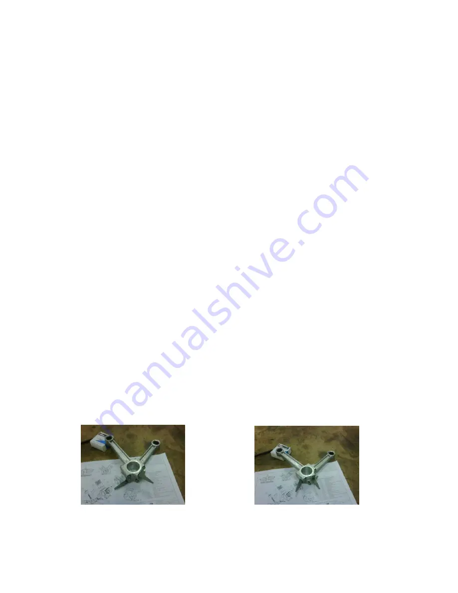
WARNING:
Incorrect installation of oil dippers can lead to insufficient lubrication and
catastrophic failure.
Incorrect Orientation Correct Orientation
Summary of Contents for RIX 2V3B-4.1V Series
Page 54: ......
Page 55: ......
Page 56: ......
Page 57: ......
Page 58: ......
Page 59: ......
Page 60: ......
Page 61: ......
Page 62: ......
Page 66: ......
Page 67: ......
Page 68: ......
Page 70: ...P N 515 910 P N 515 911 P N 515 792 P N 515 829 X515 910 X515 911 X515 792 X515 829...
Page 71: ......
Page 72: ......
Page 73: ...P N 76 713 X76 713...
Page 74: ......
Page 75: ......
Page 76: ......
Page 77: ......
Page 78: ......
Page 79: ......

