background image

MAN-2V3B-4.1V REV (E)

 26 

j. 

Reinstall the guide cylinder assembly over the guide piston. 

k. 

Reinstall the compression cylinder assemblies per instructions. 

l. 

Install distance piece covers and fill crankcase with new oil. 


7.12 

MAIN BEARINGS:  

The crankshaft is supported in the crankcase by two main bearings.  

They are a tapered roller design, consisting of an inner race, outer race and rollers.  Lubrication is 
supplied by the crankcase oil splash.   There is no scheduled maintenance for the main bearings.   


REMOVE MAIN BEARINGS

.  

a. 

The compressor must be completely disassembled.  See applicable instructions. 

b. 

Remove the flywheel and bushing by removing the three cap screws that secure the 
flywheel and bushing to the crankshaft.  Use these screws in the bushing tapped holes to 
jack the flywheel and bushing apart.  This will "unlock" the bushing from the crankshaft. 

c. 

Remove the bearing support cover and connecting rods.  NOTE:  There are notches in the 
bearing support cover gasket so that the gasket is not damaged during disassembly. 

d. 

Pull the crankshaft forward and remove it from the crankcase. 

e. 

With a suitable puller, remove the bearings from each end of the crankshaft. 


INSTALL MAIN BEARINGS

.  

a. 

Thoroughly clean the crankcase,


crankshaft and bearing cover. 


b. 

Press a new bearing on each end of the crankshaft main bearing journals. 


Preheating the 

bearings to 250˚F will facilitate installation. 

c. 

Install a new shaft seal in the crankcase. 

d. 

Install the crankshaft with bearings into the crankcase.   

e. 

Install the bearing plate with a new gasket.


Tighten the bearing plate cap screws to  30 

ft-lbs. torque. 

f. 

Install the connecting rods and guide cylinders.  Rotate by hand insure all turns freely.  
Fill the crankcase to the proper level with proper oil. 

g. 

Install the flywheel, hub and key, drive V-belts and beltguard in the reverse procedure of 
removal.  Insure that the flywheel and driver sheave are lined up.  Align V-belts and 
pulleys. 

h. 

Replace compression cylinder assemblies per instructions using special tool for piston 
rod attachment. 

j. 

Connect all other equipment in reverse order of disassembly.  

l. 

Turn the flywheel by hand a few revolutions to be certain everything is clear before 
starting the compressor. 

m. 

Start the compressor and check for gas or oil leaks.  If leakage is present, repair as 
required. 


Summary of Contents for RIX 2V3B-4.1V Series

Page 1: ...USA Phone 707 747 5900 Fax 707 747 9200 Parts Fax 707 758 0398 OPERATING INSTRUCTIONS and PARTS LIST for RIX INDUSTRIES DRY OXYGEN COMPRESSOR MODEL 2V3B 4 1V 40 PSIG Inlet 2500 PSIG Discharge S N s 12...

Page 2: ...HIGH GAS TEMP LIMITS CHANGED VALVE SERVICE INTERVAL TO 4500 HRS REMOVED REFERENCE TO 2V3 IN TITLE ADDED PRESSURE SETTING TO 203 CORRECTED pn FOR 222 NOW REV B REDRAWN B10791 ADDED DETAIL OF FRONT COVE...

Page 3: ...ure switch set points E 12 6 10 SS iii iv 2 6 9 10 11 25 Changed electrical schematic to B12726 Changed panel interior detail to A11376 Temp controller was Fuji is now Eaton new dwg A11346 Added B1257...

Page 4: ...for Electrical Panel Replaced with B12726 New Elec Wiring Diagram Replaced with new drawing A11376 Replaced with new drawing A11346 Changed description of function of machine when resetting from a hig...

Page 5: ...UBRICATION 2 2 4 ELECTRICAL CONNECTIONS 3 2 5 STORAGE 3 3 START UP AND OPERATING PROCEDURES 3 1 SYSTEM CHECKOUT 4 3 2 START UP 4 3 3 NORMAL OPERATING PRESSURE RANGES 5 3 4 RELIEF VALVE SETTINGS 5 4 CO...

Page 6: ...YLINDERS 19 7 6 PISTON RINGS 19 7 6 1 REPLACE PISTON RINGS 1st STAGE 19 7 6 2 REPLACE PISTON RINGS 2nd STAGE 20 7 6 3 REPLACE PISTON RINGS 3rd STAGE 21 7 7 PISTON RODS OIL WIPER SEALS 22 7 7 1 INSTALL...

Page 7: ...s Section B10961 Flow Schematic B11179 Plumbing Schematic A10556 General Arrangement B10791 O Ring Installation and Material Information A5089 Crankcase Assy B9131 Connecting Rod Assy 1 pin B8156 Elec...

Page 8: ...Fmax Ambient temp Flow Rate 10 SCFM 600 SCFH with 40 PSIG 100 F suction Operating Environment Indoor or weather protected Design speed 540 RPM Compressor Rotation Clockwise viewed from flywheel side D...

Page 9: ...ressed Gas Association publication CGA G 4 1 Cleaning Equipment for Oxygen Service www cganet com Any work to be done on the compressor where the gas stream may be exposed must be done in accordance w...

Page 10: ...be DEAD must be considered LIVE and dangerous at all times 4 Do not make any unauthorized alteration to equipment 5 Do not touch cylinder heads or discharge gas lines from the heads up to the heat exc...

Page 11: ...uential damages RIX certifies that all 2V3 oxygen compressors have been test run on pure oxygen gas at maximum pressures and flow rate and that the compressors are oxygen clean at shipment Purchaser t...

Page 12: ...rings are used in all stages The compression cylinders are isolated from the crankcase lubricating oil by crosshead distance pieces and metal slingers on the piston rods 1 3 GAS FLOW Gas entering at t...

Page 13: ...OF CHAPTERS 5 OR 7 Inspect all gas piping compression fittings and tighten as necessary It is not uncommon for plumbing connections to loosen during shipment CAUTION If the user gas source has the po...

Page 14: ...ion At a minimum gas suction and discharge lines should be capped The compressor should be rotated at least once every 2 months In corrosive environments the distance pieces should be sealed and the u...

Page 15: ...the gas piping A soapy water solution is one way to do this see paragraph 5 8 If interstage pressures exceed normal levels which may pop relief valves this is due to valves on the next stage leaking...

Page 16: ...st Stage 190 250 psig 2nd Stage 700 820 psig 3rd Stage up to 2500 psig Back Pressure Regulator setting 1800 psig approximate It is recommended that a log be kept noting operating pressures and mainten...

Page 17: ...switches have a cut in setting for starting and a cut out setting for stopping The deadband of each switch is adjustable See instructions in appendix for adjustments In the event of an emergency an E...

Page 18: ...h enough to close the inlet switch and the discharge switch remains closed pressure below the switch cut in setting the compressor will start c Current passes through the two closed pressure switches...

Page 19: ...torage systems connected to the compressor must be oxygen clean and constructed of oxygen compatible materials No attempt should be made to work on the machine without full knowledge of oxygen equipme...

Page 20: ...CASE LUBRICATING OIL Every 3000 hours of running time or annually whichever comes first the crankcase oil should be renewed Failing to change the oil as scheduled may result in premature or accelerate...

Page 21: ...been allowed to cool down b Systematically inspect from joint to joint and fitting to fitting in the gas system piping spraying the leak test solution c Observe for any formation of bubbles Mark the l...

Page 22: ...e 3rd stage rings must be replaced If the 2nd stage rings are also worn excessively their leak rate may prevent the 2nd stage pressure from increasing Gas leaking past either the 1st or 2nd stage ring...

Page 23: ...inlet filter or suction piping f Low suction pressure to compressor NOTE Operating compressor with a low interstage pressure may cause overheating of the final stage resulting in premature ring wear H...

Page 24: ...shing The pulleys have a hub that can be separated by removing the three bolts and using them as jacking devices by inserting into the threaded holes in the hub and tightening sequentially until the p...

Page 25: ...the User s responsibility to maintain the cleanliness of factory cleaned parts and any areas of the compressor gas stream that may be exposed to contamination during maintenance Assembly drawings inc...

Page 26: ...eliminated REED VALVE INSPECTION AND REPAIR a Inspect the reeds for cracking or pitting Remove any deposits Examine the valve seat for cracks or pits and for leakage past the seat A uniform imprint o...

Page 27: ...f the seat going into the head and the spring pin entering the small hole in the valve seat d Set the suction reed on the valve seat using a small amount of compatible O ring grease which will hold th...

Page 28: ...st be taken not to damage valve seat d Inspect and repair or replace parts as necessary All o rings must be replaced VALVE INSTALLATION a Attach the two discharge reeds on the discharge upper side of...

Page 29: ...ng for proper orientation of the valve and reeds NOTE if either reed is installed upside down the valve will not be able to open properly c Install the valve seat with the pin hole in the discharge si...

Page 30: ...ING FIXED PISTON 1ST STAGE a Remove the cylinder head per Section 7 3 b Using care to prevent side stress on the piston rod lift the cylinder off the piston Note if piston will be removed follow instr...

Page 31: ...g being certain the ends of the ring fit completely into the groove to insure proper sealing Install rings with gap 180 from the ring above d Clean and inspect the cylinder bore for wear or damage see...

Page 32: ...be changed unless the cylinder is removed c Remove cylinder Inspect condition of cylinder and piston and replace if necessary Wear must be within the tolerance specified at end of chapter d Inspect co...

Page 33: ...d in turning the rod NOTE It is recommended that the oil wiper seals be replaced anytime the rods are removed Rod surface must not exceed a finish of 16 RMS 7 7 1 INSTALL PISTON ROD and OIL SEALS a In...

Page 34: ...s of one turn The piston to cylinder head clearance will be approximately 040 inch d Tighten the jam nut to 25 ft lbs torque e Slide the oil wiper box into position pushing down hard to ensure it is f...

Page 35: ...e crankshaft surface where the oil seal makes contact Remove any burrs or scratches that might inhibit a tight seal Be careful to avoid getting any foreign material on the exposed bearing REASSEMBLY a...

Page 36: ...the connecting rod bearing bushing and crankshaft journal for proper size out of roundness or taper If the measurements are not within tolerances repair or replace as required f Inspect the wrist pin...

Page 37: ...ward and remove it from the crankcase e With a suitable puller remove the bearings from each end of the crankshaft INSTALL MAIN BEARINGS a Thoroughly clean the crankcase crankshaft and bearing cover b...

Page 38: ...ce 001 004 in Max Guide Cylinder 4 331 Dia Dia 002 in Max Guide Piston 4 325 Dia Dia 002 in Max Guide Piston to Cylinder Clearance 006 009 in Max Piston Rods 500 Dia 002 in wear Pistons 2 1 4 2 230 2...

Page 39: ...ead Nuts 30 3rd Stage Head Nuts 15 Oil Wiper Box Gland Bolts 5 Oil Wiper Box Set Screw 1 2 Piston Rod Jam Nuts 25 Distance Piece Mounting Bolts 30 Guide Cylinder Nuts 30 Connecting Rod Nuts 15 Crankca...

Page 40: ...024 5 90 3 O ring 3 4 X15 B5431 1 4 Valve Seat 1 X15 A7457 5 Valve Stop 1 2 XAO15 A5759 1 incls 1 5 Ref Dwg A5759 1 X17 757 1 Locating Pin 2 X15 B2686 2 Reed Valve 2 X123 024 5 90 3 O ring 3 X15 B4422...

Page 41: ...ck up 4 4 13 X18 C758 3G Rider Ring 2nd Stage 1 1 14 32 1186 Bolt Socket Head 10 32 3 4L GR 8 2 15 53 1040 Jam Nut 10 32 2 16 A119 B7668 Oil Wiper Box Assembly 2 incls 1 6 Ref Dwg B7668 215 A158 5 1 P...

Page 42: ...Seat 1 X15 A3719 1 8 Reed Valve Suction 1 29 X2 D2391 Head 1st Stage 1 30 105 C1993 54 Stud 1st Stage 4 31 53 4103 Hex Nut 3 8 24 12 32 20 656 Washer 3 8 24 33 32 4922 Bolt Socket Head 3 8 16 x 1 12 3...

Page 43: ...earing 1 1 8 5 C2760 Crankshaft 1 9 100 D2961 Crankcase 1 10 53 43 Nut Hex 3 8 16 8 11 1 D2962 Guide Cylinder 2 12 16 B7037 Gasket Guide Cylinder 2 2 13 105 1028 Stud 3 8 16 1 3 4L 8 14 125 1003 Shaft...

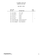
Page 44: ...214 RV1 X515 829 Relief Valve 1st Stage 300 1 215 RVI X515 910 Relief Valve Inlet 50 1 216 RV2 X515 792 Relief Valve 2nd Stage 1000 1 217 RV3 X515 911 Relief Valve 3rd Stage Set 2800 psig 1 218 CV X6...

Page 45: ...il Slinger 1 255 11 138 SDS Bushing 1 256 A142 B6201 1 Slide Base 1 265 36 2B066 Motor Sheave P1C and P1D 1 36 2B056 Motor Sheave P1A and P1B 1 267 41 B76 1 V Belt P1C and P1D 2 2 41 B75 1 V Belt P1A...

Page 46: ...X455 B6210 Tube SS 1 18 X54P 6HBUSS Union 2 19 X54P 6JBUSS Tee Union 3 20 X54P 4C5BUSS Elbow ST 4 21 X455 C2556 Tube SS 1st Stage Gauge 1 22 X455 C2557 Tube SS 2nd Stage Discharge to Hx 1 23 X455 C255...

Page 47: ...Elbow Male 2 36 54W 64X4B Tee Union 1 37 455 C2574 2 Tube Br 1 38 455 C2574 Tube Br 1 39 455 C2574 1 Tube Br 1 40 X123 904 3 O Ring 1 1 42 X54P 41 4F50GSS Adapter St Female Pipe 1 43 X54P 1 41 8PTRB P...

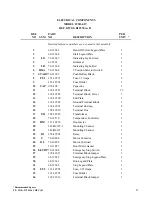
Page 48: ...minal Block 1 15 138 12591 Terminal End cap 4 16 158 12630 Terminal Box 1 17 TR 185 12629 Transformer 1 18 76 12579 Temperature Controller 1 19 HM 113 10156 Hour meter 1 20 142 B6397 3 Mounting Channe...

Page 49: ...e used copied reproduced or disclosed for any purpose without the written permission of RIX Industries RIX INDUSTRIES 4900 INDUSTRIAL WAY BENICIA CA 94510 ON SAN FRANCISCO BAY SINCE 1878 QA DRAWN DATE...

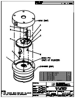
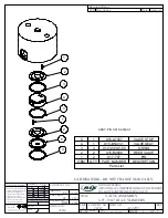
Page 50: ...7 4 X32 4171 SCREW RND HD S S 6 1 X15 C2445 VALVE PLATE 5 3 X15 A7792 REED VALVE S S 4 1 X123 025 5 O RING VITON 3 1 X123 035 5 O RING VITON 2 1 X123 045 5 O RING VITON 1 1 X123 044 5 O RING VITON ITE...

Page 51: ...uced or disclosed for any purpose without the written permission of RIX Industries Third Angle Projection Interpret Drawing Per ANSI Y14 5M 1982 Drawing Specifies The Completed Part Revision History L...

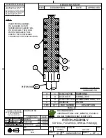
Page 52: ...isclosed for any purpose without the written permission of RIX Industries RIX INDUSTRIES 4900 INDUSTRIAL WAY BENICIA CA 94510 ON SAN FRANCISCO BAY SINCE 1878 QA DRAWN DATE PISTON ASSEMBLY 5 8 DIA FLOA...

Page 53: ...ncoiling the spiral piston ring note that each ring is slightly dish shaped The rings should be installed with the bottom of the dish down against the piston groove land 3 Gently stretch the piston ri...

Page 54: ......

Page 55: ......

Page 56: ......

Page 57: ......

Page 58: ......

Page 59: ......

Page 60: ......

Page 61: ......

Page 62: ......

Page 63: ...20 672 15 2 OIL END COVER PLATE 38 D2965 1 3 CAP CRANKCASE BREATHER 49 414 1 4 GASKET COVER 16 B7036 1 5 BALL BEARING 181 1001 2 6 CONNECTING ROD ASSY CTR CYL A7 B8156 2 7 CRANKSHAFT 2V MODEL 5 C2760...

Page 64: ...STG 3V MODEL B8156 1 1 C B RIX INDUSTRIES AIR AND GAS COMPRESSOR MANUFACTURERS ON SAN FRANCISCO BAY SINCE 1878 DD 4 12 2002 DD 4 12 2002 JFB 4 12 2002 A7 B8156 1 2 C2762 B8154 1 1 17 A8559 PIN SPLASH...

Page 65: ...INDICATING LIGHT GREEN RUNNING 1 LR 76 12628 LED INDICATING LIGHT RED SHUTDOWN 1 M 107 7072 ELECTRIC MOTOR 1 OL 76 10405 OVERLOAD 1 PSD X76 714 2500 PRESS SWITCH DISCH SET 2500 PSI 1 PSI X76 713 40 P...

Page 66: ......

Page 67: ......

Page 68: ......

Page 69: ...240 24 AMPS P1A 6 2 230VAC 60HZ H3 H4 PRIMARY X1 X2 SECONDARY 220 230 240 13 AMPS P1B 6 2 460VAC 60HZ H1 H4 PRIMARY X1 X2 SECONDARY 440 460 480 6 AMPS P1C 6 2 380VAC 50HZ H2 H4 PRIMARY X1 X2 SECONDAR...

Page 70: ...P N 515 910 P N 515 911 P N 515 792 P N 515 829 X515 910 X515 911 X515 792 X515 829...

Page 71: ......

Page 72: ......

Page 73: ...P N 76 713 X76 713...

Page 74: ......

Page 75: ......

Page 76: ......

Page 77: ......

Page 78: ......

Page 79: ......

Reviews: