REF PART
PER
NO
SYM
NO.
DESCRIPTION
UNIT
*
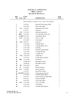
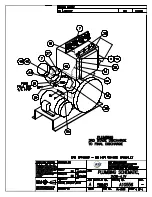
Omitted reference numbers are not used in this assembly
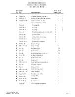
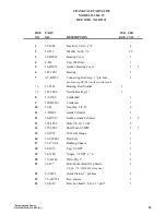
1
62-12623
Hand-Off-Auto Legend Plate
1
2
62-12624
Start Legend Plate
1
3
LG
76-12627
Indicating Light, Green
1
4
63-5514
Grommet
1
5
LR
76-12628
Indicating Light, Red
1
6
HOA
76-12604
3 Position Selector Switch
1
7
START
76-12605
Push Button, Black
1
8
FU1
163-12597
Fuse 3.5 Amps
2
9
163-12594
Fuse Holder
1
10
CAP
976-108
Capacitor
1
11
138-12587
Terminal Block
13
12
138-12589
Terminal Block, Power
3
13
138-12590
End Plate
1
14
138-12588
Ground Terminal Block
1
15
138-12591
Terminal End cap
4
16
158-12630
Terminal Box
1
17
TR
185-12629
Transformer
1
18
76-12579
Temperature Controller
1
19
HM
113-10156
Hour meter
1
20
142-B6397-3
Mounting Channel
1
21
142-B6397
Mounting Channel
1
22
R1
676-12592
Relay
1
23
C
76-10404
Motor Contactor
1
24
OL
76-10405
Motor Overload
1
25
16-11857
Hour Meter Gasket
1
26
E-STOP
76-12606
Emergency Stop Switch
1
27
138-12615
Terminal Block Jumper
3
29
62-12622
Emergency Stop Legend Plate
1
30
62-12621
Run Legend Plate
1
31
62-12625
Stop Legend Plate
1
32
FU2
163-12598
Fuse, 6.25 Amps
1
33
163-12595
Fuse Holder
1
34
138-12616
Terminal Block Jumper
1
ELECTRICAL COMPONENTS
REF. DWGS. B12570 rev B
MODEL 2V3B-4.1V
*Recommended Spares
P/N MAN-2V3B-4.1V REV (E)
37
Summary of Contents for RIX 2V3B-4.1V Series
Page 54: ......
Page 55: ......
Page 56: ......
Page 57: ......
Page 58: ......
Page 59: ......
Page 60: ......
Page 61: ......
Page 62: ......
Page 66: ......
Page 67: ......
Page 68: ......
Page 70: ...P N 515 910 P N 515 911 P N 515 792 P N 515 829 X515 910 X515 911 X515 792 X515 829...
Page 71: ......
Page 72: ......
Page 73: ...P N 76 713 X76 713...
Page 74: ......
Page 75: ......
Page 76: ......
Page 77: ......
Page 78: ......
Page 79: ......

