


IMR01N12-E7
13
3.
WIRING
This chapter describes wiring cautions, wiring layout and wiring of terminals.
3.1 Wiring Cautions
For thermocouple input, use the appropriate compensation wire.
For RTD input, use low resistance lead wire with no difference in resistance between the three lead wires.
Signal connected to Voltage input and Current input shall be low voltage defined as “SELV” circuit per
IEC 60950-1.
To avoid noise induction, keep input signal wire away from instrument power line, load lines and power lines of
other electric equipment.
Use a special shielded cable for connection with the pressure sensor.
When using our CZ-100P or CZ-200P:
The rated output value (mV/V) of pressure sensor is when the cable is at a length of 5 m. If the cable is
extended, correct the rated output value using the following equation. Set the correction value thus calculated
to “Gain setting (GAIn)” on page 67.
If there is electrical noise in the vicinity of the instrument that could affect operation, use a noise filter.
Shorten the distance between the twisted power supply wire pitches to achieve the most effective noise
reduction.
Always install the noise filter on a grounded panel. Minimize the wiring distance between the noise filter
output and the instrument power supply terminals to achieve the most effective noise reduction.
Do not connect fuses or switches to the noise filter output wiring as this will reduce the effectiveness of the
noise filter.
Allow approximately 5 seconds for contact output when the instrument is turned on. Use a delay relay when
the output line is used for an external interlock circuit.
Power supply wiring must be twisted and have a low voltage drop.
This instrument is not provided with an overcurrent protection device. For safety install an overcurrent
protection device (such as a fuse) with adequate breaking capacity close to the instrument.
Fuse type: Time-lag fuse (Approved fuse according IEC 60127-2 and/or UL 248-14)
Fuse rating: Rated current: 1.0 A
For an instrument with 24 V power supply input, supply power from a “SELV” circuit defined as IEC 60950-1.
A suitable power supply should be considered in end-use equipment. The power supply must be in compliance
with a limited-energy circuits (maximum available current of 8 A).
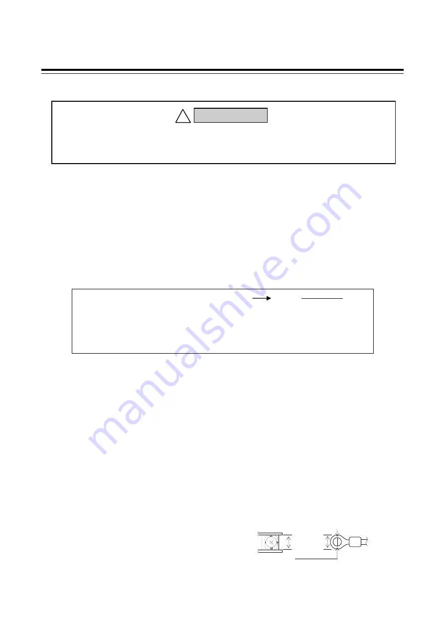
Use the solderless terminal appropriate to the screw size.
Screw size:
M3
6 (With 5.8
8 square washer)
Recommended dimension:
Recommended tightening torque:
0.4
N
・
m (4 kgf
・
cm)
Specified solderless terminals:
With
isolation
Applicable wire: Solid/twisted wire of 0.25 to 1.65 mm
2
Make sure that during field wiring parts of conductors cannot come into contact with adjacent conductive parts.
5.9 mm MAX
3.2 mm MIN
6 mm
e1: Rated output in standard-cable length 5 m (mV/V is described on the nameplate of the sensor)
e2: Rated output after extension
K: Correction factor* 1.96
10
4
/m [Non-explosionproof specification type],
1.40
10
4
/m [Explosionproof specification type]
* When using 0.5 mm
2
4-core shielded cable (standard-cable) or equal.
L:
Extended cable length (m)
e1
e2 (1
K
L)
e2
1
K
L
e1
Correction equation:
To prevent electric shock or instrument failure, do not turn on the power
until all wiring is completed. Make sure that the wiring is correct before
applying power to the instrument.
WARNING
!


