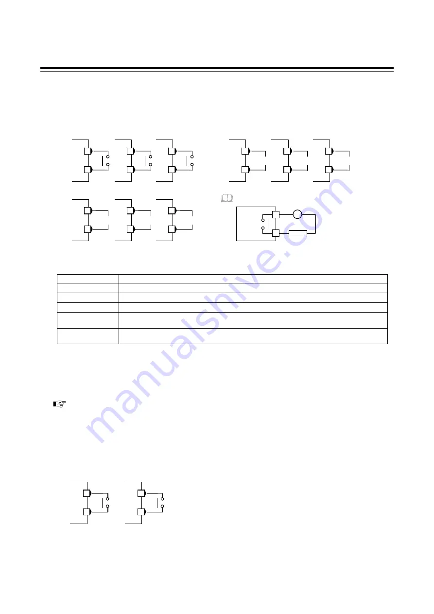
3. WIRING
IMR01N12-E7
16
Output 1 to 3 (OUT1 to OUT3)
Terminal 11 and 12 are for output 1 (OUT1); Terminal 9 and 10 are for output 2 (OUT2); and Terminal 7 and
8 are for output 3 (OUT3).
Connect an appropriate load according to the output type.
Example of wiring is as follows:
Number of outputs and output types must be specified when ordering.
Control output, Event output, or Transmission output can be allocated to output 1 to 3. The specifications of
each output are as follows.
Output type
Specifications
Relay contact output
250 V AC, 3A (Resistive load), 1a contact
Electrical life
300,000 times or more (Rated load)
Voltage pulse output
0/12 V DC (Load resistance: 600
or more)
Triac output
0.4 A (Allowable load current)
Voltage output
0 to 5 V DC, 1 to 5 V DC, 0 to 10 V DC (Load resistance: 1 k
or more)
Output resolution: 11 bits or more
Current output
0 to 20 mA DC, 4 to 20 mA DC (Load resistance: 600
or less)
Output resolution: 11 bits or more
OUT3 is isolated from both OUT1 and OUT2.
OUT1 and OUT2 are not isolated from each other except for relay or triac output. When relay or triac output is
used, there is isolation between outputs.
There is isolation between input and output.
There is isolation between output and power supply terminals.
If OUT3 is used for the Sensor power supply, refer to
■
Sensor power supply (optional)
on page 20.
Output 4 to 5 (OUT4 to OUT5)
Terminal 5 and 6 are for output 4 (OUT4); and Terminal 3 and 4 are for output 5 (OUT5).
Output type is only relay contact output.
Relay contact output
250 V AC, 1A (Resistive load), 1a contact
Electrical life
300,000 times or more (Rated load)
OUT4 and OUT5 can be used for Event output.
If OUT3 is selected for the Sensor power supply, OUT4 and OUT5 cannot be used.
Relay contact output:
NO
OUT1
12
11
NO
OUT2
10
9
NO
OUT3
8
7
Voltage pulse output/Voltage output/Current output
OUT1
12
11
OUT2
10
9
OUT3
8
7
Triac output
OUT1
12
11
OUT2
10
9
OUT3
8
7
NO
Load
Inside of
instrument
NO
OUT4
6
5
NO
OUT5
4
3


