7. SETUP SETTING MODE
IMR01N12-E7
43
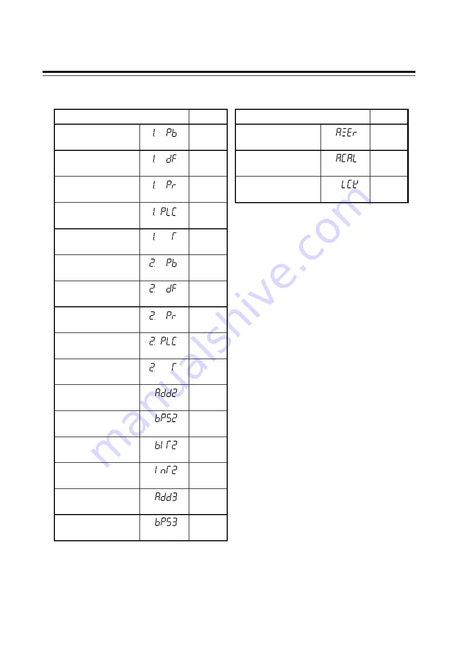
7.2 Parameter List
Parameter Page
Parameter Page
Input 1_PV bias
(1. Pb)
P. 44
Auto-zero
(AZEr)
P. 48
Input 1_PV digital
filter
(1. dF)
P. 44
Auto calibration
(ACAL)
P. 49
Input 1_PV ratio
(1. Pr)
P. 44
Set lock level
(LCK)
P. 49
Input 1_PV low input
cut-off
(1. PLC)
P. 45
Input 1_ proportional
cycle time
(1. T)
P. 45
Input 2_PV bias
(2. Pb)
P. 44
Input 2_PV digital
filter
(2. dF)
P. 44
Input 2_PV ratio
(2. Pr)
P. 44
Input 2_PV low input
cut-off
(2. PLC)
P. 45
Input 2_ proportional
cycle time
(2. T)
P. 45
Device address
(Slave address)
(Add2)
P. 46
Communication speed
(bPS2)
P. 46
Data bit configuration
(bIT2)
P. 46
Interval time
(InT2)
P. 47
Infrared
communication address
(Add3)
P. 47
Infrared
communication speed
(bPS3)
P. 47


