


8. ENGINEERING MODE
IMR01N12-E7
63
8.4 Screen Configuration (F10)
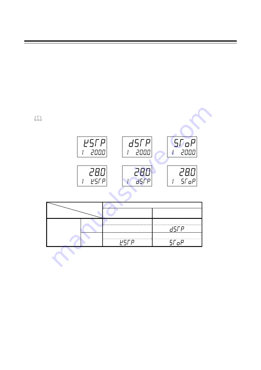
STOP display selection (SPCH)
STOP message for control STOP mode can be displayed either on the upper display or the lower display.
SPCH is to select the display to show the STOP message.
Data range:
0: Displays on the Measured value (PV1/PV2) unit (TYPE 1)
1: Displays on the Set value (SV) unit (TYPE 2)
Factory set value:
0
There are three different characters for STOP mode depending on how to be transfered from RUN to
STOP.
Display explanations:
RUN/STOP with Event input
RUN
(Contact closed)
STOP
(Contact open)
RUN
RUN STOP
RUN/STOP with
key operation
STOP is not displayed
(dSTP)
STOP STOP
STOP
(KSTP)
(SToP)
Bar graph display selection (dE)
Use to select the contents of the bar graph display.
Data range:
0:
No
display
1:
Input 1_manipulated output value (MV)
2:
Input 1_measured value (PV)
3:
Input 1_set value (SV)
4:
Input 1_deviation value
5: Unused
(Not
available)
6:
Input 2_manipulated output value (MV)
7:
Input 2_measured value (PV)
8:
Input 2_set value (SV)
9:
Input 2_deviation value
Factory set value:
0
Related parameters:
Bar graph resolution setting (P. 64)
Continued on the next page.
TYPE1:
TYPE2:
AREA
SV
PV1
(KSTP)
AREA
SV
PV1
(dSTP)
AREA
SV
PV1
(SToP)
AREA
SV
PV1
(KSTP)
AREA
SV
PV1
(dSTP)
AREA
SV
PV1
(SToP)


