


8. ENGINEERING MODE
IMR01N12-E7
76
8.8 Output (F30)
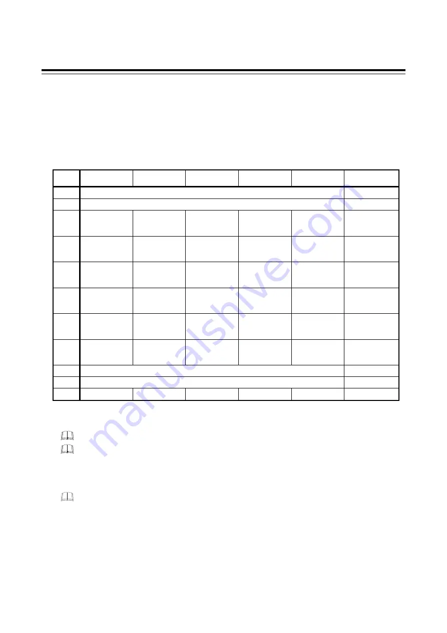
Output logic selection (LoGC)
This is used to assign the output function (control output, event, etc.) for the output (OUT1 to OUT5).
Data range:
1 to 11 (Refer to the following table)
1, 2, 9 and 10: Unused (Not available)
[Output Assignment Table]
(M: Relay contact output, V: Voltage pulse output, R: Current output, E: Voltage output, T: Triac output)
Set
value
OUT1
(M/V/R/E/T)
OUT2
(M/V/R/E/T)
OUT3
(M/V/R/E/T)
OUT4
(M)
OUT5
(M)
Remarks
1
This set value is not used for the HA430/930.
2
This set value is not used for the HA430/930.
3
MV1
EV3 (Energized)
or
EV4 (Energized)
EV2
(Energized)
EV1
(Energized)
FAIL
(De-energized)
Energized alarm
corresponding to
FAIL output
4
MV1
EV3 (De-energized)
or
EV4 (De-energized)
EV2
(De-energized)
EV1
(De-energized)
FAIL
(De-energized)
De-energized alarm
corresponding to
FAIL output
5
MV1
MV2 EV4
(Energized)
EV3
(Energized)
EV1 (Energized)
or
EV2 (Energized)
Energized alarm
corresponding to
two loops control
6
MV1
MV2 EV4
(De-energized)
EV3
(De-energized)
EV1 (De-energized)
or
EV2 (De-energized)
De-energized alarm
corresponding to
two loops control
7
MV1
MV2 EV3
(Energized)
or
EV4 (Energized)
EV2
(Energized)
EV1
(Energized)
Energized alarm
corresponding to
two loops control
8
MV1
MV2 EV3
(De-energized)
or
EV4 (De-energized)
EV2
(De-energized)
EV1
(De-energized)
De-energized alarm
corresponding to
two loops control
9
This set value is not used for the HA430/930.
10
This set value is not used for the HA430/930.
11
MV1
EV4 (Energized)
EV 3 (Energized)
EV 2 (Energized)
EV 1 (Energized)
Energized alarm
MV 1
Manipulated output value of Input 1, MV 2
Manipulated output value of Input 2,
EV 1
Output of Event 1, EV 2
Output of Event 2, EV 3
Output of Event 3, EV 4
Output of Event 4, FAIL
FAIL output
An output logic becomes
OR
output when two or more output functions are assigned to one output.
When three transmission outputs are selected, the transmission outputs are automatically assigned to
OUT1 through OUT3 and it has priority over the Output logic selection (LoGC). To select
Manipulated output value of Input 1 or Input 2 as output type of OUT1, OUT2 or OUT3, select “1.
MV: Input 1_manipulated output value (MV)” or “2. MV: Input 2_manipulated output value (MV)” at
the parameters of Transmission output type selection.
The OUT3 output terminals (No. 7 and 8) are used when any sensor power supply is specified. The
use of this function disables the use of OUT3 to OUT5 as control output, event output and
transmission output. In addition, the number of transmission output points becomes 2 maximum.
Factory set value:
For
1-input
controller:
3
For 2-input controller: 5
Related parameters:
Output timer setting (P. 77),
Alarm lamp lighting condition setting (P. 77),
Event type selection
(P. 80), Transmission output type selection (P. 79)


