


IMS01P12-E1
3
For Heat/Cool PID control (V-TIO-M), Input channel 2
becomes unused.
For Heat/Cool PID control (V-TIO-M), Control output 1
corresponds to the heating output and Control
output 2 corresponds to the cooling output.
Heater break alarm (HBA) function cannot be used
when control output is Voltage/Current output.
Control loop break alarm (LBA) function cannot be
used when control type is Heat/Cool PID control
(V-TIO-M).
If any of the products are missing, damaged, or if your
manual is incomplete, please contact RKC sales office
or the agent.
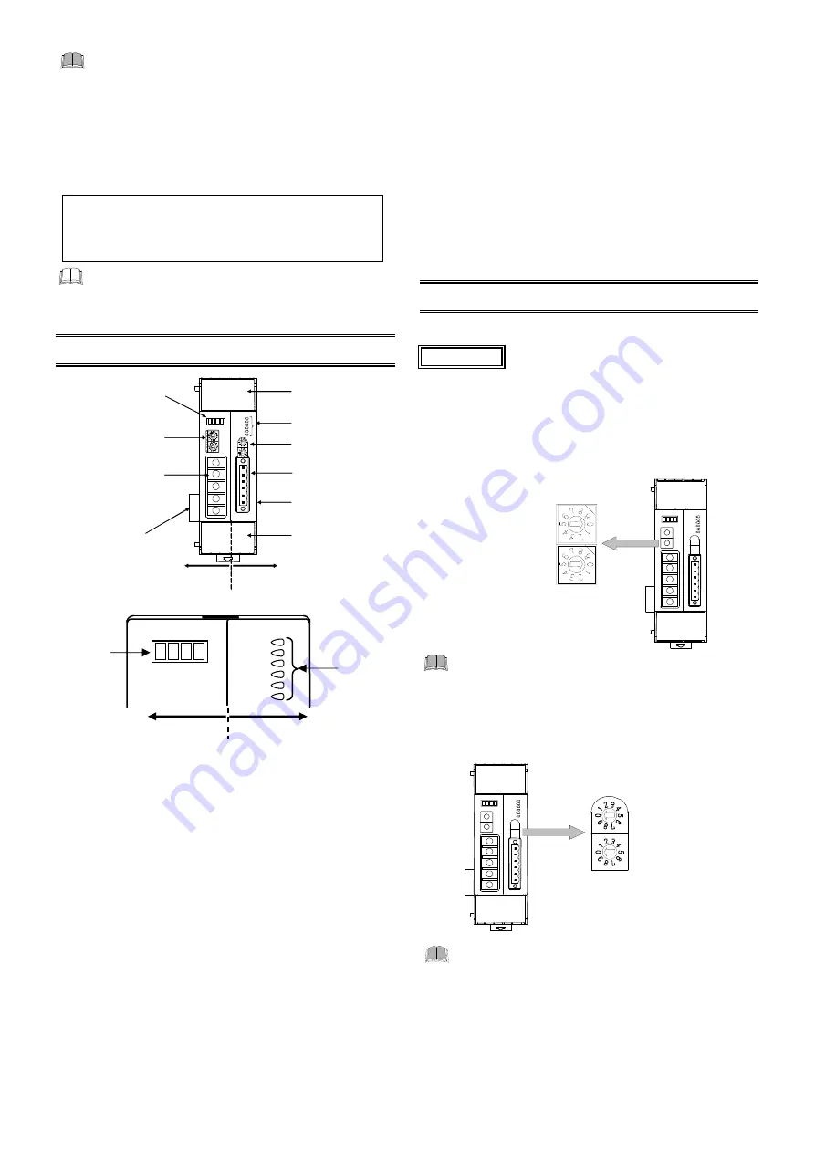
3. PARTS DESCRIPTION
FA
IL
RU
N
ON
L
TX
/R
X
FAIL/RUN
R X/TX
EVENT1
EVENT2
EVENT3
EVENT4
Terminal cover
Indication lamps 1
Module address
setting switch
Terminal cover
Joint connector
(Right-side)
Joint connector
(Left-side)
Indication lamps 2
Station number
setting switch
CC-Link connection
terminals
(COM.PORT)
CC-Link side
Temperature control side
Event input/output
connector
*
FAIL/RUN
RX/TX
EVENT1
EVENT2
EVENT3
EVENT4
FA
IL
RU
N
SD
RD
[Indication lamps 1]
FAIL/RUN (for temperature control side)
When normally:
A green lamp turns on (RUN)
When abnormally: A red lamp turns on (FAIL)
RX/TX (for host communication)
During data send and receive: A green lamp turns on
EVENT 1 to 4
Display various states by setting.
During ON state: A green lamp turns on
Display contents
Event 1 state, Event 2 state, Comprehensive event state, Output state,
and Control state
[Indication lamps 2]
FAIL (for CC-Link side)
When normally:
A red lamp turns off
When abnormally: A red lamp turns on
When station number, communication speed
setting abnormal
:
A red lamp turns on
In an station number, communication speed
setting change
:
A red lamp is flashing (0.4 seconds cycle)
When
CC-Link communication stopped/
internal
communication normal:
A red lamp is flashing (1 second cycle)
RUN
When normally (for internal communication):
A green lamp turns on
When abnormally (for internal communication):
A green lamp is flashing (0.5 seconds cycle)
In
validation of the module which it connected just after
the power is turned on
:
A green lamp is flashing (0.1 seconds cycle)
When
CC-Link communication stopped state:
A green lamp turns off
SD
During CC-Link data send:
A green lamp turns on
RD
During CC-Link data receive: A green lamp turns on
4. COMMUNICATION SETTING
Set communication setting before mounting and wiring of SRV.
Do not separate the module mainframe from the terminal
base with the power turned on. If so, instrument failure may
result.
4.1 Station Number Setting
Set a station number of CC-Link. For this setting, use a small
slotted screwdriver.
Setting range: 1 to 61
Factory set value: 0
Station number setting switch
High-order digit
setting
(Set value
10)
Low-order digit
setting
(Set value
1)
No communication with CC-Link can be conducted
with each factory set value (0) left as it is. Always set
the station number.
4.2 Module Address Setting
Set an address of module. For this setting, use a small slotted
screwdriver.
Module address setting switch
High-order digit
setting
(Set value
10)
Low-order digit
setting
(Set value
1)
Setting range: 0 to 30
Factory set value: 0
When setting module address, always set their
address from address number “0” in succession.
Otherwise, problems or malfunction may result.
For host communication (Modbus), the value
obtained by adding “1” to the set address
corresponds to the address used for the actual
program.
Set the module address such that it is different to
the other addresses on the same line. Otherwise,
problems or malfunction may result.
Indication
lamps 2
Indication
lamps 1
Temperature control side
CC-Link side
Accessories
End Plate ....................................................................... 2
Joint connector cover .................................................... 2
V-TIO-L/V-TIO-M Instruction Manual (IMS01P12-E1) ... 1
* Installed when provided with the event input/output (optional).
CAUTION


