


IMS01P12-E1
4
4.3 Number of Occupied Stations/
Extended Cyclic Setting
With the DIP switch 1 which there is on the left side of module,
select
Number of occupied station/Extended cyclic
, CC-Link/Host
communication and communication speed for internal communication
in CC-Link.
Internal communication is communication that
V-TIO-L/V-TIO-M
module conduct to other temperature
control modules in CC-Link.
Left side view (CC-Link side)
Dip switch 1
1 2 3 4 5 6 7 8
ON
1 2 3 4 5 6 7 8
ON
OFF
1
2
Internal communication speed
OFF OFF
38400 bps
ON OFF
9600
bps
OFF ON
19200
bps
ON ON
38400
bps
Factory set value: 38400 bps
3 4 5
Number of occupied stations/
Extended cyclic
OFF OFF OFF
4 stations occupied 1 time (8 CH assignment)
ON OFF OFF
4 stations occupied 1 time (16 CH assignment)
OFF ON OFF
4 stations occupied 2 times (16 CH assignment)
ON ON OFF
4 stations occupied 2 times (32 CH assignment)
OFF OFF ON
4 stations occupied 4 times (32 CH assignment)
ON OFF ON
4 stations occupied 4 times (62 CH assignment)
Factory set value: 4 stations occupied 1 time (8 CH assignment)
6
Host communication protocol (CC-Link side)
OFF RKC
communication
ON Modbus
Factory set value: RKC communication
7 CC-Link/Host
communication
selection
OFF CC-Link (Internal communication validity)
ON Host communication (Internal communication invalidity)
Factory set value: CC-Link (Internal communication validity)
Switch No. 8: OFF fixed (Do not change the factory
set values)
[Factory set value]
Internal communication speed: 38400 bps
Number of occupied stations/extension cyclic:
4 stations occupied 1 time (8 CH assignment)
Host communication: RKC communication
CC-Link/Host communication:
CC-Link (Internal communication validity)
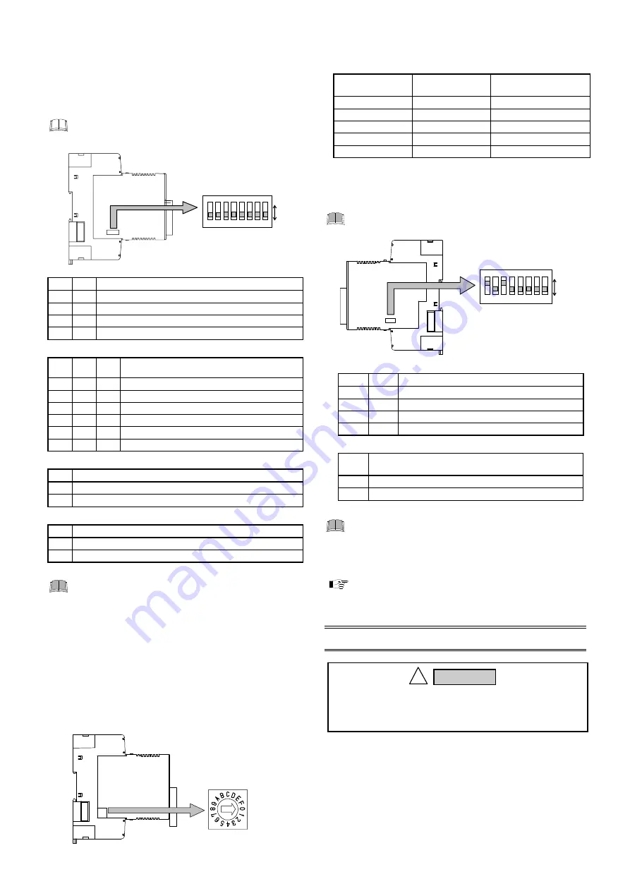
4.4 CC-Link Communication Speed Setting
With the rotary switch which there is on the left side of module,
select communication speed for CC-Link. For this setting, use a
small slotted screwdriver.
Setting range: 0 to 4
(Factory set value: 0)
Communication speed
setting switch
Left side view (CC-Link side)
Communication speed and maximum transmitter distance
(maximum length of Network)
[Use CC-Link dedicated cable Ver.1.10]
Communication
speed setting
Communication
speed
Maximum
transmitter distance
0
156 kbps
1200 m
1
625 kbps
900 m
2
2.5 Mbps
400 m
3
5 Mbps
160 m
4
10 Mbps
100 m
4.5 Host Communication Setting
With the DIP switch 2 which there are on the right side of module,
select communication speed for host communication.
When host communication is not used, DIP switch 2
need not be set.
Right side view (temperature control side)
Dip switch 2
1 2 3 4 5
6
7
8
ON
1 2 3 4 5
6
7
8
ON
ON
OFF
1
2
Host communication speed
OFF
OFF
2400 bps
ON
OFF
9600 bps
OFF
ON
19200 bps
ON
ON
38400 bps
Factory set value: 9600 bps
6
Host communication protocol
(temperature control side)
OFF
RKC communication
ON
Modbus
Factory set value: RKC communication
Switch No. 3 to 5 and 7, 8: Do not change the factory
set values
[Factory set value]
Host communication speed:
9600 bps
Host communication protocol: RKC communication
For host communication, refer to the
Module Type
Controller SRV Communication Instruction Manual
(IMS01P01-E
)
.
5. MOUNTING
5.1 Mounting Cautions
(1) This instrument is intended to be used under the following
environmental conditions.
(IEC61010-1)
[OVERVOLTAGE CATEGORY II, POLLUTION DEGREE 2]
(2) Use this instrument within the following environment conditions:
Allowable ambient temperature:
10 to
50
C
Allowable ambient humidity:
5 to 95 %RH
(Absolute humidity: MAX. W. C 29 g/m
3
dry air at 101.3 kPa)
Installation environment conditions: Indoor use
Altitude up to 2000 m
To prevent electric shock or instrument failure, always
turn off the power before mounting or removing the
instrument.
!
WARNING


