


IMS01P12-E1
6
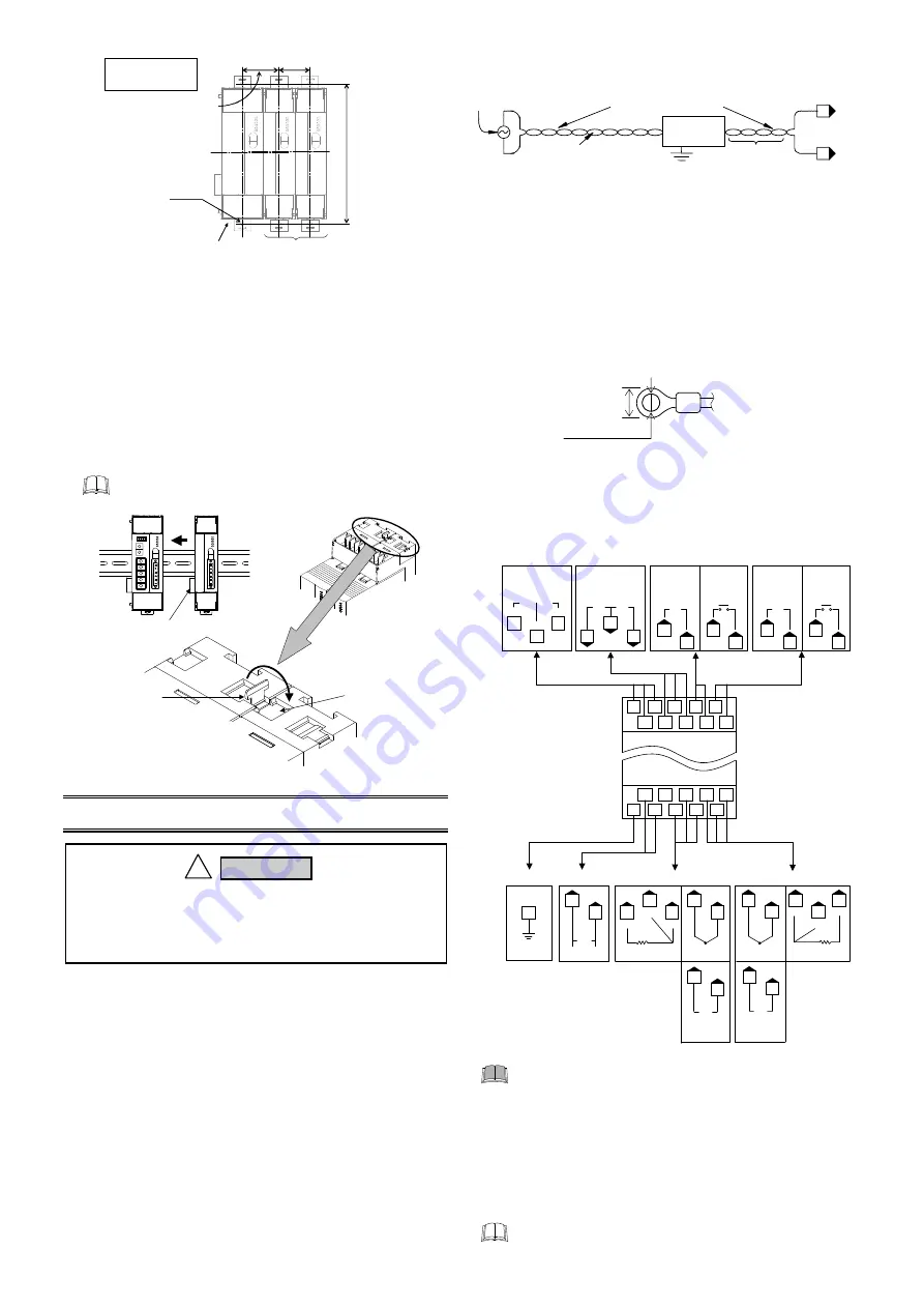
5.5 Jointing Each Module
Up to 30 modules (V-TIO-A, V-TIO-B, V-TIO-C or V-TIO-D) can
be connected to one module (V-TIO-L or V-TIO-M).
Joint these
modules according to the following procedure.
Jointing procedure
1.
Mount the modules on the DIN rail and then joint these
modules together with the joint connector while sliding the
relevant module.
2.
Lift each of the joint tabs located at the top and bottom of the
module and then insert it in the slot of the adjacent module to
fix these two modules.
For panel mounting, first joint each module and then
mount it on the panel.
Joint tab
When viewed
from top
There is one joint tab at
each of the top and bottom
of on module. Therefore, fix
two adjacent modules with
these two joint tabs.
Joint tab
insertion slot
Joint connector
6. WIRING
6.1 Wiring Cautions
For thermocouple input, use the appropriate compensation wire.
For RTD input, use low resistance lead wire with no difference
in resistance between the three lead wires.
To avoid noise induction, keep input signal wire away from
instrument power line, load lines and power lines of other
electric equipment.
Signal connected to Voltage input and Current input shall be
low voltage defined as “SELV” circuit per IEC 60950-1.
If there is electrical noise in the vicinity of the instrument that
could affect operation, use a noise filter.
- Shorten the distance between the twisted power supply wire
pitches to achieve the most effective noise reduction.
-
Always install the noise filter on a grounded panel.
Minimize the wiring distance between the noise filter output
and the instrument power supply terminals to achieve the
most effective noise reduction.
- Do not connect fuses or switches to the noise filter output
wiring as this will reduce the effectiveness of the noise filter.
Power supply wiring must be twisted and have a low voltage drop.
For an instrument with 24 V power supply input, supply power
from "SELV" circuit defined as IEC 60950-1.
A suitable power supply should be considered in the end-use
equipment. The power supply must be in compliance with a
limited-energy circuits (maximum available current of 8 A).
In the maximum configuration (extension up to 31 modules) the
24 V DC supplied equipment may draw up to 4 A. The power
supply shall be capable of delivering at least 4 A.
Use the solderless terminal appropriate to the screw size.
- Screw size:
M3 x 6
- Recommended tightening torque: 0.4 N
m [4 kgf
cm]
- Specified solderless terminals:
With isolation
Make sure that during field wiring parts of conductors can not
come into contact with adjacent conductive parts.
6.2 Terminal Configuration
CT1
T/R(B)
SG
T/R(A)
RS-485
Internal communication
or
Host communication
CT input
Control output 1
Control output 2
15
Relay contact
NO
OUT1
Voltage pulse/
Current/
Voltage
OUT1
5
2
5
2
3
6
7
16
17
24 V
DC
Power supply
Ground
Thermocouple
TC1
Input channel 1
Voltage/
Current
IN1
RTD
RTD1
B
B
A
NO
OUT2
OUT2
4
1
4
1
10
13
10
14
13
13
10
TC2
IN2
9
12
8
12
12
9
RTD2
B
B
A
9
Input channel 2
19
18
20
FG
16
15
3
2
1
17
7
6
5
4
20
19 14 13 12
18
11 10
9
8
Upper-side terminal
CT2
Relay contact
Voltage pulse/
Current/
Voltage
Lower-side terminal
Thermocouple
RTD
Voltage/
Current
Voltage/
Current
For Heat/Cool PID control (V-TIO-M), Input channel 2
becomes unused.
For Heat/Cool PID control (V-TIO-M), Control output 1
corresponds to the heating output and Control
output 2 corresponds to the cooling output.
Heater break alarm (HBA) function cannot be used
when control output is Voltage/Current output.
Control loop break alarm (LBA) function cannot be
used when control type is Heat/Cool PID control
(V-TIO-M).
Terminal No. 11 is not used.
Mounting
dimensions
OUT
Minimize
distance
Instrument
power
terminals
IN
Twist these leadwires
Shorten distance between
pitches
Instrument power
Noise filter
13
0.
5
0.
2
35.25
0.2
30
0.2
M3
Module of 40.5 mm wide
Module of 30 mm wide
(Unit: mm)
5.9 mm or less
3.2 mm or more
To prevent electric shock or instrument failure, do not
turn on the power until all wiring is completed. Make
sure that the wiring is correct before applying power to
the instrument.
!
WARNING


