EAGLE 2 Operator’s Manual
Description • 165
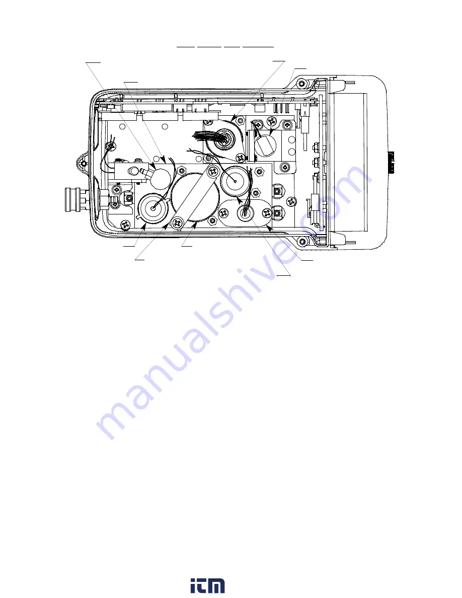
Figure 37: Typical ESM-01 Sensor Location
The ESM-01 sensor is installed in a single sensor flow chamber which is located in the
area next to the standard 4-sensor flow chamber. This area can accommodate up to three
single sensor flow chambers. Although the EAGLE 2 can support up to three ESM-01
sensors, many combinations are impractical for various reasons including sensor cross
sensitivity to other gases. Consult RKI Instruments, Inc. for practical combinations.
Figure 37 above illustrates a typical ESM-01 sensor location in front of the pump. The
ESM-01 flow chamber may also be installed in one of the other two sensor chamber
locations depending on the particular version of the EAGLE 2. Some ESM-01 instrument
configurations do not include the 4-sensor flow chamber.
ESM-01 Sensor
The ESM-01 sensor is a cylindrical sensor with a diffusion opening on the front and a 12
pin circular connector on the back. A 12 wire cable plugs into the back of the ESM-01
sensor with a circular connector that includes a locking lever. The other end of the cable
plugs into an ESM-01 sub PCB (see description below) that is installed on the main PCB.
The sensor is held in the ESM-01 flow chamber by a bracket on standoffs.
ESM-01 Sub PCB
The ESM-01 sub PCB is a circuit board that is installed on the main PCB in one of the 3
sub PCB positions when an ESM-01 sensor is used with the EAGLE 2. The ESM-01
sensor connects to the sub PCB with a 12-position connector. The sub PCB plugs into the
main PCB and is held in place with a screw/flat washer/lock washer. There are no user
serviceable parts on the ESM-01 sub PCB.
CO Sensor
Pump
LEL Sensor and
Sensor Bracket
Charcoal Filter
Oxygen Sensor
Bracket
H2S Sensor
Top Case Not Shown
Standard Flow Chamber
Oxygen Sensor
ESM-01 Sensor
www.
.com
information@itm.com
1.800.561.8187

