18 • Instrument Description
EAGLE 2 Operator’s Manual
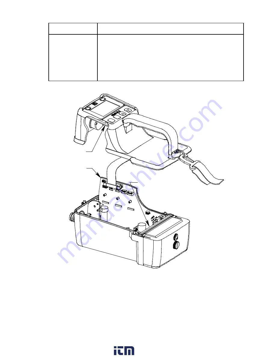
Printed Circuit Boards (PCBs)
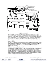
Figure 4: EAGLE 2 PCBs
The EAGLE 2’s PCBs analyze, record, control, store, and display the information
collected. The main PCB and I.S. barrier PCB are located in the bottom case. The display
PCB is located in the top case. The display PCB and I.S. barrier PCB are not user
serviceable and are not involved in any user performed maintenance. The main PCB is not
user serviceable, but it is involved in the replacement of sensors, so it is described below.
RANGE
▼
SHIFT
• changes the detection units of the combustible gas channel
(when Catalytic Units is set to
CHANGE OK
in Setup Mode)
• silences and resets audible alarm if Alarm Latching is set to
Latching
and Alarm Silence is set to
ON
• enters instructions into the EAGLE 2’s microprocessor
• moves the cursor on the LCD down the screen
• decreases the value of a parameter available for adjustment
• scrolls through parameter options
Table 3: EAGLE 2 Control Button Functions
Button
Function(s)
Main PCB
Display PCB
I.S. Barrier PCB (not visble)
www.
.com
information@itm.com
1.800.561.8187


