180 • Maintenance
EAGLE 2 Operator’s Manual
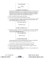
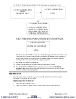
The buzzer and alarm LEDs activate in a double pulsing pattern. Press and release the
POWER ENTER RESET button to reset the alarm and continue to the Calibration
Mode Screen. Attempt to calibrate the ESM-01 channel again. If the failure
continues, investigate the cause. See “Troubleshooting” on page 67.
34. Disconnect the tubing from the probe.
35. Unscrew the demand flow regulator from the calibration cylinder.
36. Use the RANGE
▼
SHIFT button to place the cursor next to the
NORMAL
OPERATION
menu option, then press and release the POWER ENTER RESET
button to return to Measuring Mode.
Maintenance
The SO
2
and HCN ESM-01 sensors are the only ESM-01 sensors that include user
serviceable parts. This section includes a procedure for replacing an ESM-01 sensor and
for replacing the H
2
S scrubber in the SO
2
and HCN sensors. When replacing a sensor, you
may either replace it with another of the same sensor or you may install a different ESM-
01 sensor. If a different one is installed, the EAGLE 2 will load the sensor parameters and
configure the ESM-01 channel for the new sensor.
Replacing the ESM-01 Sensor or Changing Sensor Type
1. Verify that the EAGLE 2 is off.
2. Place the EAGLE 2 upside down on a flat surface or hold it upside down.
3. Unscrew the three case screws until they disengage from the top case. They are
captive screws so they will not fall off of the bottom case.
4. Turn the EAGLE 2 right side up and carefully lift the top case away from the bottom
case. Be careful not to lift it so far that it pulls on the main PCB with the cable that
connects the top case to the main PCB.
5. Lay the top case down next to the bottom case to allow access to the flow system.
6. Locate the ESM-01 sensor. It has a twelve wire cable with a connector that mates to
an ESM-01 sub PCB that is installed on the main PCB and is normally located next to
the pump. Figure 37 on page 165 shows an ESM-01 sensor in a typical location.
7. Unscrew and remove the two screws that hold down the ESM-01 sensor bracket.
8. Grasp the sensor firmly and pull it out of the ESM-01 flow chamber. Rock it back and
forth gently if necessary to pull it out. Take care not to pull the cable from the sub
PCB.
9. Rotate the locking lever counterclockwise on the cable connector that mates to the
ESM-01 sensor to unlock it.
10. Unplug the old ESM-01 sensor from the cable.
11. Connect the new ESM-01 sensor to the sensor cable and rotate the locking lever
clockwise to lock the connector.
12. Insert the sensor into the ESM-01 flow chamber and push it in until it bottoms out.
13. Line up the holes in the ESM-01 sensor bracket with the two standoffs on the ESM-01
chamber.
14. Install the two sensor bracket screws.
www.
.com
information@itm.com
1.800.561.8187


