EAGLE 2 Operator’s Manual
Instrument Description • 19
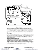
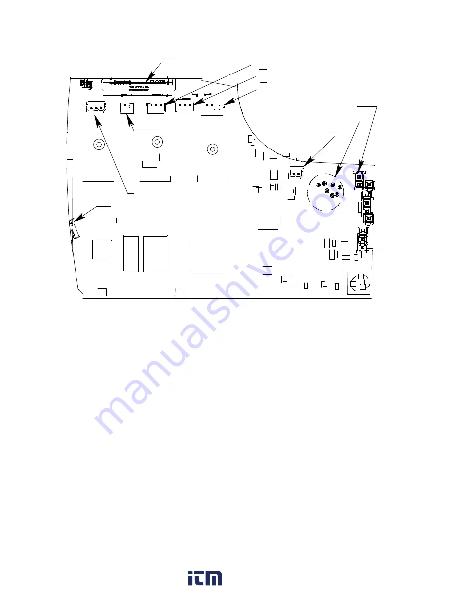
Figure 5: Main PCB
The main PCB is located on the right side of the bottom case. It slides into guiding
grooves at the bottom, front, and rear of the bottom case. It is held in place by the top case.
Connectors for the sensors, differential pressure switch, pump, display PCB, optional float
probe, and I.S. barrier PCB are located on the main PCB. In addition, an IR transmitter/
receiver is located at the front of the PCB behind the IR port on the front of the bottom
case.
Alarm LEDs
Two sets of red alarm LEDs (light emitting diodes) are visible through two raised, frosted
plastic lenses in the top case. Each set has two LEDs. They are above the LCD, one above
the left corner and one above the right corner. The alarm LEDs alert you to gas, low
battery, and failure alarms.
Infrared Communications Port
An infrared (IR) communications port is located on the left front of the bottom case when
the instrument is viewed from the front. The data transmitted through the port is in
standard IrDA protocol. A computer’s infrared port or an IrDA/USB cable connected to a
USB port can be used to download data saved by the EAGLE 2 to a computer using the
Eagle 2 Data Logger Management Program. See the Data Logger Management Program
operator’s manual for data logging and downloading instructions.
Oxygen Connector Pins (OXY)
I.S. Barrier Connector
LEL Connector (HC)
CO Connector (CO)
H2S Connector (H2S)
Pump Connector
Float Probe Connector
Display connector
IR Communication Sensor/Transmitter
DP Switch Connector
www.
.com
information@itm.com
1.800.561.8187


