212 • Maintenance
EAGLE 2 Operator’s Manual
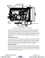
11. Connect the new infrared CO
2
sensor to the sensor cable and rotate the locking lever
clockwise to lock the connector.
12. Insert the sensor into the infrared CO
2
flow chamber and push it in until it bottoms
out.
13. Line up the holes in the infrared CO
2
sensor bracket with the two standoffs on the
infrared CO
2
chamber.
14. Install the two sensor bracket screws.
15. Confirm that the main PCB is seated in its slots and that its bottom edge is resting on
the bottom of the bottom case. If the main PCB is not seated properly, it may be
damaged when the top case is re-installed.
16. Make sure that the top case gasket is fully seated in its groove and carefully put the
top case back on the bottom case. If you have any difficulty mating the top and
bottom cases, inspect the placement of the main PCB and the placement of the top
case gasket.
17. Turn the EAGLE 2 upside down and tighten the three case screws to secure the top
case to the bottom case.
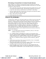
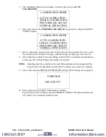
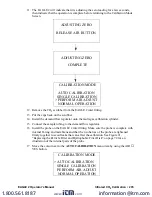
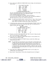
18. Calibrate the infrared CO
2
channel as described in “Infrared CO
www.
.com
information@itm.com
1.800.561.8187

