background image


46 • Chapter 5: Operation

Icon View vs. Details View

GX-3R (Pro)s that are currently connected or have been previously connected can be viewed in either 
Icon View or Details View. Choose Icon or Details View by clicking the 

Icon

 or 

Details

 radio button 

below the control buttons. 

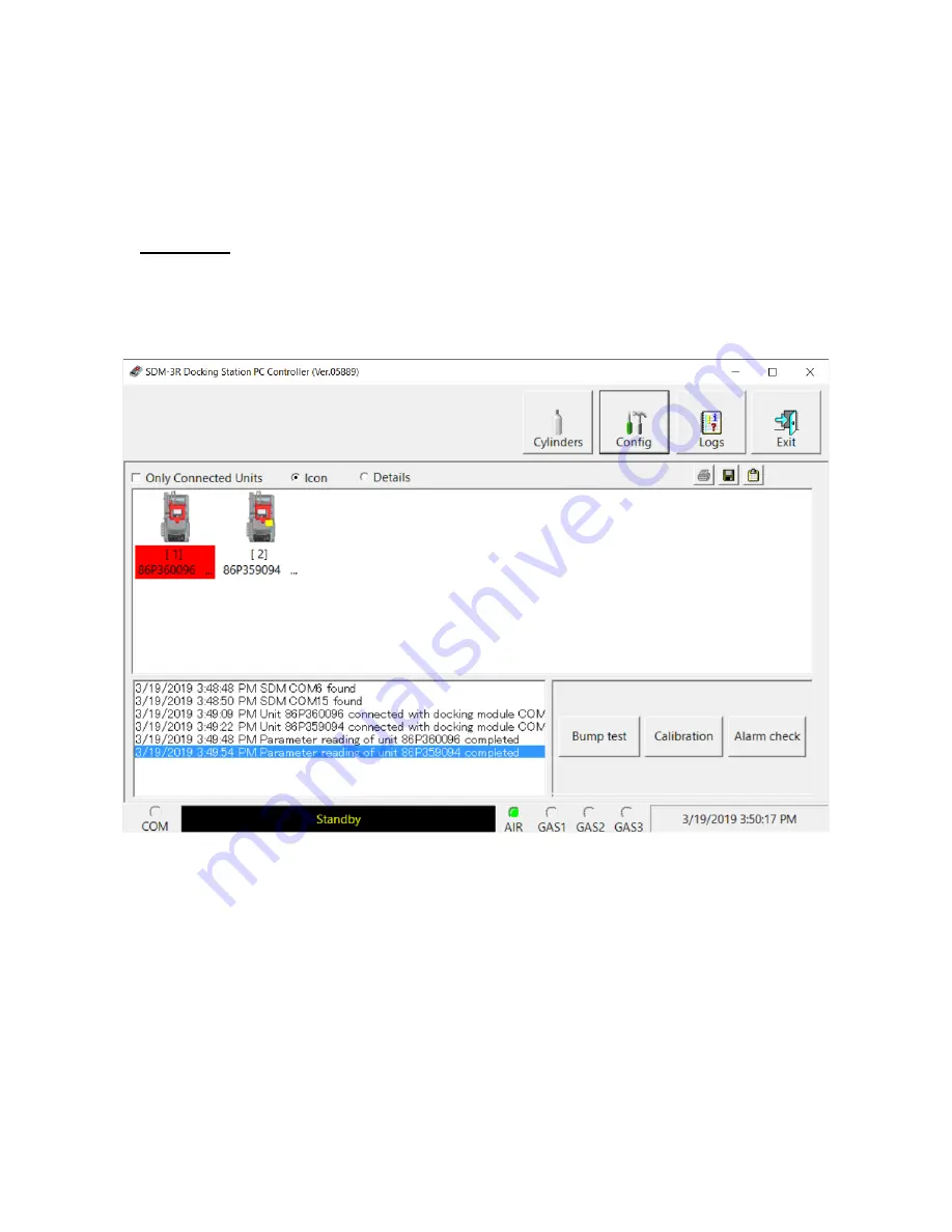
Icon View

Icon View allows you to view connected GX-3R (Pro)s and previously connected GX-3R (Pro)s in an 
icon configuration. Connected GX-3R (Pro)s are shown as a GX-3R (Pro) inserted in an SDM-3R 
icon. Previously connected GX-3R (Pro)s are shown as GX-3R (Pro) icons. Right clicking a GX-3R 
(Pro) causes the Instrument Function Menu to appear. 

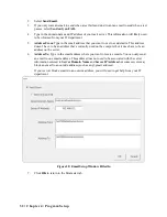
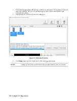
 Figure 26: Main Program Window, Icon View

Summary of Contents for SDM-3R

Page 1: ...www rkiinstruments com SDM 3R Docking Station PC Controlled Configuration Operator s Manual Part Number 71 0488 Revision P1 Released 5 24 19 ...

Page 2: ...ocal repair costs transportation costs or contingent expenses incurred without our prior approval THIS WARRANTY IS EXPRESSLY IN LIEU OF ANY AND ALL OTHER WARRANTIES AND REPRESENTATIONS EXPRESSED OR IMPLIED AND ALL OTHER OBLIGATIONS OR LIABILITIES ON THE PART OF RKI INSTRUMENTS INC INCLUDING BUT NOT LIMITED TO THE WARRANTY OF MERCHANTABILITY OR FITNESS FOR A PARTICULAR PURPOSE IN NO EVENT SHALL RKI...

Page 3: ...nnections Back Panel 12 Standard Accessories 13 Air Filter and Exhaust Tubing 13 Single Station AC Adapter 13 USB Cable 14 Ethernet Cable 14 USB Drive 14 Optional Accessories 14 Multi Station AC Adapter 14 Connection Brackets 14 Wall Mounting Brackets 15 Cylinder Holder 15 Chapter 3 Hardware Setup 16 Overview 16 Connecting Multiple SDM 3Rs Together Optional 16 Hardware Assembly 18 Wall Mounting th...

Page 4: ...rument Connection 41 Overview of the SDM 3R PC Controller Program 41 PC Program Functions 41 Main Program Window 42 Connecting GX 3R Pro s 43 Icon View vs Details View 46 Printing and Exporting an Instrument List from the Main Window 48 Automatic Procedures 49 Performing a Bump Test 49 Performing a Calibration 56 Performing an Alarm Check 63 Chapter 6 Changing SDM 3R Parameters 65 Entering the SDM...

Page 5: ...larm Trend Data 107 Calibration Data 111 Event Data 117 Interval Trend Data 119 Memo Data 123 Bump Test Data 125 Alarm Check Data 129 Deleting Data in the Logs Window 130 Chapter 10 Instrument Function Menu 131 Overview 131 Open Function 132 Edit Function 132 Reload Function 132 Download Logs Function 133 Clear Logs Function 133 Power Off Function 133 Chapter 11 Spare Parts List 134 CAUTION Read a...

Page 6: ...anual is to explain how to set up and use the SDM 3R in PC Controlled configuration It also explains how to use the SDM 3R Docking Station PC Controller Program You will learn how to install and launch the SDM 3R Docking Station PC Controller Program setup the PC Program for use with the SDM 3R prepare the SDM 3R for use bump test and calibrate up to 10 GX 3R Pro s using the PC Controlled configur...

Page 7: ...R Docking Station PC Controlled Configuration Operator s Manual uses the following conventions for notes cautions and warnings NOTE Describes additional or critical information CAUTION Describes potential damage to equipment WARNING Describes potential danger that can result in injury or death Cautions Safety Information Use only polyurethane sample tubing with the SDM 3R Consult RKI Instruments I...

Page 8: ...aximum Number of Records Saved Bump test 214 OR Calibration 200 OR Alarm check 468 Number of Calibration Gas Cylinders Infinite if you change cylinders during a test Standard Accessories Instruction Manual SDM 3R Docking Station PC Controller Software Inlet Air Filter 10 Foot Long Exhaust Tube USB Cable Type A to Type B Ethernet Cable Single Station AC Adapter USB Drive Available Accessories Multi...

Page 9: ...e red door before you perform a bump test calibration alarm check or charge a GX 3R Pro An infrared IR port at the rear of the cradle lines up with the GX 3R Pro s IR port when it is inserted in the cradle and is used to communicate with the instrument A charging jack engages with the GX 3R Pro when you close the red door Figure 1 Instrument Cradle GX 3 R O F F PO W ER C O PY C HAR G E 1 S EC O N ...

Page 10: ...n passed Red calibration failed EDIT ENTER none Green alarm check passed Red alarm check failed COPY none Off no records saved Green More than 20 of SDM 3R memory remains Orange Less than 20 of SDM 3R memory remains Red No memory available Oldest records will be deleted as new records are created POWER Turns SDM 3R on off POWER button s LED is labelled CHARGE Solid green no GX 3R Pro installed or ...

Page 11: ...ive The GAS 2 and GAS 3 fittings are only active if the docking station was ordered with 2 or 3 solenoid valves respectively The right side of the SDM 3R is shipped from the factory with a small panel attached to it with two screws That panel should remain in place if the SDM 3R is being used alone or if it is the right most station in a bank of connected stations The panel needs to be removed in ...

Page 12: ...network Power Jack The rectangular power jack is located on the far right side of the back panel The SDM 3R uses the same charger as the GX 3R Pro The plug on the end of the AC adapter cable mates to the power jack If desired you can use the screw included with the AC adapter to ensure the cable does not disconnect from the SDM 3R Exhaust Fitting An exhaust fitting is located on the right side of ...

Page 13: ...disperse WARNING Do not use an exhaust tube that is longer than 15 feet The increased flow restriction caused by a longer tube may affect gas response and cause inaccurate calibration and bump test results Single Station AC Adapter The single station AC adapter is a wall plug style adapter with a 4 foot cable The end of the cable has a plug that connects to the SDM 3R s power jack A screw included...

Page 14: ...ional Accessories Multi Station AC Adapter The multi station AC adapter is a wall plug style adapter that plugs into a bar The bar has five 4 foot cables coming out one side The end of each of the five cables has a plug that connects to the SDM 3R s power jack The AC adapter is rated 100 240 VAC input 5 99 VDC output USB Hub If you have more docking stations than you have available USB ports you w...

Page 15: ...ed using 2 mounting brackets See Wall Mounting the SDM 3R Optional on page 18 for a description of how many wall mounting brackets are needed depending on how many SDM 3Rs are in your system Cylinder Holder A cylinder holder allows a calibration cylinder to securely sit on a desktop or benchtop ...

Page 16: ...er 2 For every station except the one that will be located on the far right side of the bank a Unscrew the two screws that retain the panel on the right side of the station The screws are not captive Be sure not to lose them b Pull the panel away from the SDM 3R c Use needle nosed pliers to remove the clear plugs that are installed in the four mating sample fittings d Save the panel the screws and...

Page 17: ...ocedure The last station installed should be the one that still has a panel on the right side 5 Optional Use the metal connection brackets and screws sold separately to secure the two connection points on the bottom of the SDM 3R to each other Figure 9 Connecting SDM 3Rs Together Back Panel ...

Page 18: ...5 Install the 10 foot long 5 16 inch ID flexible tube that is included with the SDM 3R on the exhaust fitting Route the tube to an area where the exhaust can be safely dispersed such as an open window Exhaust tubing from multiple SDM 3Rs cannot be manifolded together CAUTION The maximum recommended length for the exhaust tube is 15 feet Using tubing longer than 15 feet or with an ID smaller than 5...

Page 19: ...ardware Setup 19 Figure 10 Wall Mounting 1 7 SDM 3Rs of SDM 3Rs 1 SDM 3R 5 7 SDM 3Rs 2 4 SDM 3Rs 4 wall mounting brackets Total of wall mounting brackets necessary 2 wall mounting brackets 6 wall mounting brackets ...

Page 20: ...e SDM 3R s using the provided screws The wall mounting brackets are not straight They have a short section and a long section The short section has a smaller hole than the long section Screw the short section into the SDM 3R making sure that the long section goes away from the station and is flush with the back of the SDM 3R 8 10 SDM 3Rs of SDM 3Rs 8 wall mounting brackets Total of wall mounting b...

Page 21: ...into are appropriate to support the weight of the system Installing the Cylinder Holder Optional 1 Choose a location for the calibration cylinders that is close to the SDM 3R 2 4 pads with adhesive on each side are included with each cylinder holder 3 Remove the backing from one side of each pad and stick it to a corner on the bottom of the Short Section w Smaller Hole Long Section w Bigger Hole S...

Page 22: ...ordered with 2 or 3 solenoid valves respectively AIR The AIR fitting needs either 1 A demand flow regulator and a cylinder of zero emissions air OR 2 A fresh air area GAS 1 Recommended Gas RKI Instruments Inc recommends using one of the following for the GAS 1 fitting 1 A 4 gas mix LEL O2 CO H2S for GX 3R Pro s that have an H2S sensor OR 2 A 3 gas mix LEL O2 CO for GX 3R Pro s that do not have an ...

Page 23: ...resh air area or connect a cylinder of zero air with a demand flow regulator to the Instrument Types Recommended Calibration Gas Cylinder and Gas Inlet Selection 3 gas LEL Oxy CO GAS 1 3 gas mix with LEL Oxy CO 3 gas LEL Oxy CO CO2 GAS 1 3 gas mix with LEL Oxy CO GAS 2 N2 GAS 3 CO2 3 gas LEL Oxy CO SO2 GAS 1 3 gas mix with LEL Oxy CO GAS 2 SO2 4 gas LEL Oxy CO H2S GAS 1 4 gas mix with LEL Oxy CO H...

Page 24: ...he calibration gas cylinder s NOTE Do not connect pressurized gas directly to the SDM 3R Be sure to install a demand flow regulator on the cylinder before connecting it to the SDM 3R 3 Connect the demand flow regulator to the appropriate inlet fitting using 3 16 inch ID sample tubing ...

Page 25: ...instruments com sdm3r 4 Click on the Download tab 5 Click the SDM 3R PC Controller Software link 6 A zip file will begin to download Save the zip file 7 Extract the contents of the zip file 8 Double click the setup exe file 9 The SDM 3R Docking Station PC Controller InstallShield Wizard comes up to guide you through installation Follow the InstallShield Wizard instructions 10 A Device Driver Windo...

Page 26: ...tion ensure that your docking station or the master docking station if you plan to have a bank of them are connected to your computer 15 Turn on the docking station by flipping the power switch to the ON position 16 The first time an SDM 3R is turned on after being connected to the computer the SDM 3R needs some time to be recognized by the computer The status bar will indicate that the drivers ar...

Page 27: ...ned cylinders that are fairly common If a cylinder that you need to use is not on this list you can define your own cylinder Selecting a Cylinder from the Predefined List The Cylinders Window comes with several predefined cylinders that you can choose from 1 Click Start on the Windows Icon Tray then select Programs SDM 3R You may also double click the shortcut created on your desktop 2 If you are ...

Page 28: ...e drop down menu that appears Use the calendar to choose an expiration date The expiration date box will be highlighted in orange if the expiration date of the cylinder is less than 10 days away The expiration date box will be highlighted in red if the expiration date has passed 8 Select or deselect the Active box If Active is selected the PC Program will alert you at start up if the cylinder has ...

Page 29: ...cally generated 4 If you want to enter a part number for the cylinder double click in the Part No field and type in a part number This field is normally used for an RKI part number 5 Set the expiration date by clicking in the Expiration field and clicking the drop down menu that appears Use the calendar to choose an expiration date The expiration date box will be highlighted in orange if the expir...

Page 30: ...llows you to update parameters that only affect PC Program operation view database information and change the password to enter the Configuration Window Parameter Tab The Parameter Tab allows you to view or change bump test and calibration settings that only apply to the PC Program operation Changing anything in the Parameter Tab of the Config Window does not change any settings in the SDM 3R and ...

Page 31: ...mes up to save the settings and return to the Main Window Email The PC Program can be configured to send emails out whenever an instrument is bump tested calibrated or alarm checked An example of an alarm check email is shown below 1 Click Email Figure 19 Email Setup Window Blank ...

Page 32: ...ve to be an address that s currently used on the computer but it does have to be an address on the server 6 Address To Type in the email address where you want to receive emails You can only send an email to one email address This address does not need to be associated with the server information entered in Server Domain Name and Server IPAddress but some servers may block an email to an outside a...

Page 33: ... this parameter is set to 0 seconds the GX 3R Pro will not be turned off after a successful bump test calibration or alarm check Data Logger Section Down Load Data Logger Selected Instrument data is automatically downloaded based on the Down Load Interval setting Deselected factory setting Instrument data is not automatically downloaded Instrument data can always be manually downloaded Clear After...

Page 34: ...om 0 seconds to 3600 seconds factory setting is 60 seconds Calibration Section If neither Manual Calibration nor Auto Calibration is selected you will not be able to perform a calibration Select the box for the desired operation Manual Calibration Selected factory setting A manual calibration can be performed by selecting an instrument or instruments in the main program window and clicking Calibra...

Page 35: ...0 second wait period the sensor s pass bump testing the gas application will be stopped and the test will move on to the next sensor s or to the fresh air purge If the gas reading on any of the tested channels is outside of the bump test tolerance defined in Tolerance below at the end of the 10 second gas application and a 10 second wait period the bump test will fail and the next step will depend...

Page 36: ... on your instrument sensor configurations Tolerance The Tolerance can be set between 10 and 50 The factory setting is 50 It determines how close the instrument gas reading must be to the calibration gas concentration for each channel during a bump test in order to pass the bump test It is defined as a percentage of the calibration gas concentration The amount that the instrument gas reading differ...

Page 37: ...lick OK The default password is ABCDE case sensitive 3 Click the Database tab 4 The default database location is displayed at the top of the Database tab The default database file name is SDMLog mdb 5 Click the button to the right of the current location It has three dots on it 6 Navigate to a new location where a database exists click on the database to select it and click Open The new database l...

Page 38: ...the Database tab 4 Click the Import button located along the left side of the Database Tab 5 Select an existing mdb file that you wish to import You can import a mdb file that was created on another computer and moved to your computer you can select a file that was generated on your computer using the Create button or you can navigate to another network computer s mdb file The default location for...

Page 39: ...er and Password tabs 10 Click OK and then click Yes in the window that comes up to save the settings and return to the Main Window Password Tab The password Tab allows you to change 3 passwords Config Window Allows access to the Configuration Window The password can be up to 12 characters long and contain any letter number or symbol It is case sensitive Factory setting is ABCDE Open Edit Maintenan...

Page 40: ...dow click on the Password tab 2 For each password enter the new password in the top box and confirm it in the bottom 3 Make any other desired changes in the Parameter and Database tabs 4 Click OK and then Yes to confirm the changes and return to the Main Window ...

Page 41: ... and calibrations can be performed on multiple GX 3R Pro s GX 6000s EAGLE 2s and other GX type instruments simultaneously Follow all instructions in the appropriate docking station manuals as well as the instructions in this manual Overview of the SDM 3R PC Controller Program This section provides a brief overview of the program and a description of the main program window Instructions for using t...

Page 42: ...onnected to it are also shown The program s various functions are initiated or accessed from this screen The current date and time are always displayed in the lower right corner of the main program window Figure 23 Parts of the Main Program Window Control Buttons The Cylinders Config Logs and Exit control buttons are located along the top right of the window The Bump test Calibration and Alarm che...

Page 43: ... with the docking station s To the right of the communications port indicator is the status field It displays the current status of the program It can indicate if the software is in standby mode or if it is downloading data among other indications Fitting Indicators To the right of the status field are 4 round fitting indicators They correspond to the AIR and GAS fittings on the left side of the S...

Page 44: ...a GX 3R and down for a GX 3R Pro 10 Close the red door The GX 3R Pro will automatically turn on and connect to the SDM 3R 11 Repeat step 1 step 10 for any additional SDM 3Rs and GX 3R Pro s 12 For each GX 3R Pro the PC Program will indicate that a GX 3R Pro was found and it will download the instrument s basic parameters NOTE Turn each GX 3R Pro on 10 15 seconds after the previous instrument to mi...

Page 45: ...time on the PC Program s screen Figure 25 GX 3R Pro s Connected and Downloaded 14 If a GX 3R Pro is due for calibration the docking station number and instrument serial number will be highlighted in red 15 If a GX 3R Pro is due for calibration within the next 10 days the docking station number and instrument serial number will be highlighted in orange 16 If a GX 3R Pro s basic parameters could not...

Page 46: ...n or Details radio button below the control buttons Icon View Icon View allows you to view connected GX 3R Pro s and previously connected GX 3R Pro s in an icon configuration Connected GX 3R Pro s are shown as a GX 3R Pro inserted in an SDM 3R icon Previously connected GX 3R Pro s are shown as GX 3R Pro icons Right clicking a GX 3R Pro causes the Instrument Function Menu to appear Figure 26 Main P...

Page 47: ...ously connected GX 3R Pro s in a table format Scrolling to the right in Details View allows you to view existing GX 3R Pro parameters For a description of these parameters and instructions to change them see Chapter 7 Changing GX 3R Pro Parameters on page 78 Figure 27 Main Program Window Details View ...

Page 48: ...etails format The list cannot be printed when viewed in Icon format Printing the Instrument List 1 Select the Details radio dot near the top of the Main Window Figure 28 Details View 2 Click the Print icon located just below the Logs button 3 Click OK in the window that appears Saving the Instrument List to a csv File 1 Click the Save icon located just below the Logs button 2 Choose a file path an...

Page 49: ... to complete Automatic Bump Test or Calibration If Auto Bump Test or Auto Calibration is selected in the Parameter Tab of the Configuration Window the PC Program will automatically bump test or calibrate a connected GX 3R Pro as long as a bump test or calibration is due on that instrument See Parameter Tab on page 30 for a description of these parameters The use of this feature allows the user to ...

Page 50: ...he SDM 3R See pg 22 for calibration gas cylinder options and calibration gas connection procedures 4 Highlight the GX 3R Pro s you wish to bump test Figure 29 Instrument Selection 5 Click Bump test in the lower right corner of the main program window NOTE A bump test cannot be started if a GX 3R is installed with the yellow lever down ...

Page 51: ...et gas are being bump tested The gas concentration shown next to each gas name is the auto calibration value for that gas If it does not match the gas concentration listed on the cylinder change the auto calibration value for the instrument s associated with that gas See Sensor Tab on page 94 for instructions Figure 30 GAS 1 Selection 7 Select the gases that will use GAS1 and click OK ...

Page 52: ... assign the remaining gases all to GAS3 The program will prompt you to change the cylinder during the bump test Use the selection box below each inlet assignment to select or deselect that gas for bump testing NOTE Your SDM 3R will only have as many gas inlet choices as it has solenoid valves For example an SDM 3R with only one solenoid valve will only have GAS1 as a choice 10 Click OK 11 You will...

Page 53: ...The PC Program performs a zero adjustment and analyzes the results If any sensors failed the zero adjustment the bump test for that instrument is aborted 14 The SDM 3R then applies calibration gas in the order of the gas inlets for the length of time defined in Gas Exposure Time in the Config Window If Fast Bump is selected in the Config window gas is applied for 10 seconds then the pump stops and...

Page 54: ...mp Fails is selected in the Config window the gas keeps flowing and a calibration automatically begins Figure 33 Calibration Gas Flowing 16 Once the calibration is over the SDM 3R continues with the next gas application 17 After calibration gas is applied the docking station purges with fresh air for 15 seconds Figure 34 Fresh Air Purge ...

Page 55: ...n to the main program window or double click an instrument information line to view the bump test and or calibration results in the Logs window 20 For all bump test result outcomes the GX 3R Pro s are displayed in the main program window in Details View To return the main program window to Icons View click the Icons radio button 21 All bump test results can be viewed in the Logs window See Bump Te...

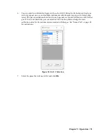
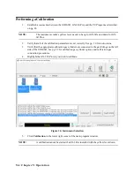
Page 56: ...t correctly See pg 30 for instructions 3 Verify that the appropriate calibration gas cylinders are connected to the gas fittings on the left side of the SDM 3R See pg 22 for calibration gas cylinder options and calibration gas connection procedures 4 Highlight the GX 3R Pro s you wish to calibrate Figure 36 Instrument Selection 5 Click Calibration in the lower right corner of the main program wind...

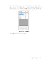
Page 57: ...t gas are being calibrated The gas concentration shown next to each gas name is the auto calibration value for that gas If it does not match the gas concentration listed on the cylinder change the auto calibration value for the instrument s associated with that gas See Sensor Tab on page 94 for instructions Figure 37 GAS 1 Selection 7 Select the gases that will use GAS1 and click OK ...

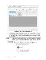
Page 58: ...than 3 gases assign the remaining gases all to GAS3 The program will prompt you to change the cylinder during the calibration Use the selection box below each inlet assignment to select or deselect that gas for bump testing NOTE Your SDM 3R will only have as many gas inlet choices as it has solenoid valves For example an SDM 3R with only one solenoid valve will only have GAS1 as a choice 10 Click ...

Page 59: ... GX 3R Pro was not on for 40 seconds before the bump test was initiated air will flow until the GX 3R Pro has been on for 40 seconds Figure 39 Air Flowing 13 The PC Program performs a zero adjustment and analyzes the results If any sensors failed the zero adjustment the calibration for that instrument is aborted 14 The SDM 3R then applies calibration gas in the order of the gas inlets for 60 secon...

Page 60: ...60 Chapter 5 Operation 15 The SDM 3R analyzes the results after the end of each gas application Figure 40 Calibration Gas Flowing ...

Page 61: ...Chapter 5 Operation 61 16 After calibration gas is applied the docking station purges with fresh air for 15 seconds Figure 41 Fresh Air Purge ...

Page 62: ...click an instrument information line to view the calibration results in the Logs window 19 For all calibration result outcomes the GX 3R Pro s are displayed in the main program window in Details View To return to Icons View click the Icons radio button 20 All calibration results can be viewed in the Logs window See pg 111 for instructions for viewing calibration data ...

Page 63: ...uzzer The PC Program analyzes the alarm check results and determines if the GX 3R Pro passed the alarm check 1 Establish a connection between the SDM 3R GX 3R Pro and the PC Program as described on pg 43 NOTE The instrument cradle s yellow lever needs to be up for GX 3Rs and down for GX 3R Pros 2 Highlight the GX 3R Pro s you wish to alarm check Figure 43 Instrument Selection 3 Click Alarm Check i...

Page 64: ...the main program window or double click an instrument information line to view the alarm check results in the Logs window 8 For all alarm check result outcomes the GX 3R Pro s are displayed in the main program window in Details View To return to Icons View click the Icons radio button 9 All alarm check results can be viewed in the Logs window See pg 129 for instructions for viewing alarm check dat...

Page 65: ...bs Bump Cal 1 Bump Cal 2 Internal Automatic A station s settings can be saved to a file and a file can be imported using this window Entering the SDM Window 1 Open the PC Program 2 Confirm that the AC adapter is connected to the SDM 3R and to an AC wall socket 3 Connect the Type A to Type B USB cable to the SDM 3R and to an available USB port on your computer 4 Press the SDM 3R s POWER button When...

Page 66: ...ration 5 Right click on the SDM icon 6 Click Open SDM S 7 If the Password parameter in the Bump Cal 2 Tab of the SDM Window is selected factory setting is deselected the program prompts you for a password to enter the SDM Window Enter the password and click OK ...

Page 67: ... 6 Changing SDM 3R Parameters for Standalone Operation 67 8 The SDM Window opens and the Bump Cal 1 Tab is displayed Each tab in the SDM Window is described in the sections that follow Figure 45 Bump Cal 1 Tab ...

Page 68: ...68 Chapter 6 Changing SDM 3R Parameters for Standalone Operation Bump Cal 1 Tab This section describes the Bump Cal 1 Tab of the SDM Window Figure 46 Bump Cal 1 Tab ...

Page 69: ... Auto Bump Selected On Deselected Off Deselected Off AIR Flush 15 120 seconds 15 seconds GAS 20 120 seconds 20 seconds AIR Purge 5 120 seconds 15 seconds Tolerance 10 50 50 Fast Bump Selected On Deselected Off Selected On Auto Cal if Bump Fails Selected On Deselected Off Selected On Alarm Check Selected On Deselected Off Selected On Auto bump if past due Selected On Deselected Off Deselected Off C...

Page 70: ...bump test It is defined as a percentage of the calibration gas concentration The amount that the GX 3R Pro gas reading differs from the calibration gas concentration must be equal to or less than this percentage of the calibration gas concentration For example if the tolerance is set to 50 and the LEL calibration gas concentration is 50 LEL then the bump test gas reading for the LEL channel on the...

Page 71: ...e bump test or calibration The LEDs turn on for a few seconds the buzzer sounds and the SDM 3R determines if these actions were completed successfully Deselected An LED and buzzer test is not done at the end of a bump test or calibration Auto bump if past due for bump only Selected If the connected GX 3R Pro is due for a bump test the SDM 3R automatically performs a bump test on all channels immed...

Page 72: ...bration only Selected factory setting A calibration can be manually initiated using the SDM 3R s CAL button Deselected A calibration cannot be manually initiated using the SDM 3R s CAL button Auto cal if past due for calibration only Selected If the connected GX 3R Pro is due for a calibration the SDM 3R automatically performs a calibration on all channels immediately after the GX 3R Pro is connec...

Page 73: ...e Data Logger Interval parameter is described below NOTE A data download takes approximately 2 minutes to complete Data Logger Interval The Data Logger Interval is the length of time in days that will pass before data is automatically downloaded from a GX 3R Pro if Data Logger Auto Download is set to Interval It can be set anywhere from 1 to 60 days The factory setting is 1 day Use the arrows to t...

Page 74: ... bump test calibration or alarm check Auto Power Off This is the length of time that passes after the last operation is finished before the program will automatically shut off the GX 3R Pro If a successful bump test calibration or alarm check is performed the program will automatically shut off the GX 3R Pro in the time defined in Power Off After Pass regardless of the Auto Power Off setting Use t...

Page 75: ...b The Internal Tab is used for setting up a LAN connection on a non DHCP network and does not have any function in the SDM 3R s PC Controlled Configuration Instructions for using the Internal Tab can be found in the SDM 3R Standalone Configuration Manual Figure 48 Internal Tab ...

Page 76: ...red day s If a GX 3R Pro is installed in an SDM 3R at the specified day time the SDM 3R will turn the GX 3R Pro on perform the test then turn the GX 3R Pro off 1 Use the drop down menu to select Bump Test Calibration or Alarm Check Only 1 test can be selected Multiple tests cannot be done automatically 2 Highlight the hours or minutes portion of the Execute Time and then use the arrows to change t...

Page 77: ...e Import File button on the right side of the SDM Window to load a parameter configuration file that can be uploaded to the SDM 3R The parameter configuration files have a sdm extension and are only readable by the PC Program See Exporting an SDM File on page 77 for a description of how to create and save a parameter configuration file When you upload a parameter configuration file you are uploadi...

Page 78: ... Yes in the window that comes up to save the changes Parameter Tab This tab allows you to view and change various instrument parameters and settings and has information in four sub tabs the Disp Mode Tab the User Mode 1 Tab the User Mode 2 Tab and the Maintenance Mode Tab The table below lists the instrument parameters shown in the Parameter Tab along with the parameter s available choices and the...

Page 79: ...me pg 86 GX 3R GX 3R Pro 0 5 minutes and 1 99 min utes in 1 minute increments 5 minutes Beep Select pg 87 GX 3R GX 3R Pro OFF LED Buzzer LED Buzzer BUMP CAL ALARM ALERT BUMP CAL ALARM OFF Need to get Bump Log GX 3R GX 3R Pro selected deselected deselected Language pg 87 GX 3R Pro English Japanese Spanish German French Portuguese Russian Korean Italian English Date Format pg 88 GX 3R Pro DD MM YYYY...

Page 80: ...elected selected Cal Past Due Act pg 89 GX 3R GX 3R Pro Confirm to Cal Must Calibrate Notification Only Confirm to Cal Cal Check Gas pg 89 GX 3R Pro 4GAS ALL ALL Man Down pg 89 GX 3R Pro selected deselected deselected Panic pg 89 GX 3R Pro selected deselected deselected Warning 1 Time pg 89 GX 3R Pro 10 120 sec 60 sec Warning 2 Time pg 90 GX 3R Pro 10 120 sec 75 sec Alarm Time pg 90 GX 3R Pro 10 1...

Page 81: ...ec 120 sec 90 sec Maintenance Mode Tab ID Display pg 92 GX 3R GX 3R Pro selected deselected deselected Disp Suppress pg 92 GX 3R GX 3R Pro selected deselected deselected Disp Follower pg 93 GX 3R GX 3R Pro selected deselected deselected Restore Def pg 93 GX 3R GX 3R Pro n a n a Alarm Latching pg 93 GX 3R GX 3R Pro selected deselected selected Auto Fresh Air Adj pg 93 GX 3R GX 3R Pro selected desel...

Page 82: ...on ID 4 To change the station ID list see Station User Tab on page 96 User ID The current user ID will display If you want to select a new user ID 1 Go to the Station User tab 2 Click Read for the user ID 3 Go back to the Parameter tab and use the drop down menu to select the desired user ID 4 To change the user ID list see Station User Tab on page 96 Cal Interval Day The calibration interval is t...

Page 83: ...as maintenance records noting when a sensor or a battery pack was changed The Memo section is empty until the user enters information The first time information is entered a Memo file is created in the Logs window If the Memo is changed in the same operating session that Memo file is updated When the GX 3R Pro is disconnected from the PC Program and connected again a new Memo file is created with ...

Page 84: ...cetylene C2H4 ethylene C2H6 ethane C2H5OH ethanol C3H6 propylene C3H6O acetone C3H8 propane C4H6 butyne C5H10 cyclopentane C6H6 benzene n C6H14 hexane C7H8 toluene n C7H16 heptane C8H10 xylene n C9H20 nonane EtAc ethyl acetate IPA isopropyl alcohol MEK methyl ethyl ketone MMA methyl methacrylate DME dimethyl ether MIBK methyl isobutyl ketone THF tetrahydrofuran Figure 50 Parameter Tab Disp Mode Su...

Page 85: ...3R Pro Only Selected LCD has a black background with white characters Deselected factory setting LCD has a white background with black characters Buzzer Volume GX 3R Pro Only Low Buzzer volume is low High factory setting Buzzer volume is high Data Log Overwrite Selected factory setting The GX 3R Pro writes over the oldest data with new data when the data logger memory is full Deselected The GX 3R ...

Page 86: ...of the value to make your selection or highlight the existing value and enter the desired value Beep Time Min The Beep Time Min parameter defines how often the confirmation alert or non compliance indicator occurs It can be set at any time but it only applies if the Beep Select parameter is set to something other than OFF The available choices are 0 5 minutes and 1 99 minutes in 1 minute increment...

Page 87: ...ndication can occur if any of the following happens Bump test is due and Bump Test Time Remaining is set to Confirm to Bump or Notification Only Calibration is due an Cal Reminder is set to Confirm to Cal or Notification Only Instrument goes into any gas alarm The instrument s LEDs will double flash as often as defined in Beep Time Min To clear a bump non compliance you must perform a successful b...

Page 88: ... from the last time the GX 3R Pro was used or start collecting new readings and reset the time in operation Deselected factory setting The GX 3R Pro automatically starts new TWA and PEAK reading collection and resets the time in operation at startup User Mode Password Selected The GX 3R Pro prompts you for a password when you enter User Mode The box to the right of this selection allows the user t...

Page 89: ... GX 3R Pro will display that a calibration is due but will continue with the warm up sequence Cal Check Gas GX 3R Pro Only 4 GAS The calibration dates for only the standard 4 sensors LEL O2 H2S and CO are used to determine if a calibration is due ALL factory setting The calibration dates for the standard 4 sensors along with the IR CO2 or super toxic sensor are used to determine if a calibration i...

Page 90: ...arning 1 Time Alarm Time GX 3R Pro Only The Alarm Time is the amount of time will pass between a Man Down detection and the main alarm It can be set in 1 second increments from 10 120 seconds The factory setting is 90 seconds Alarm Time Warning 2 Time Warning 1 Time User Mode 2 Sub Tab Bump Reminder Selected The GX 3R Pro will give an indication at start up if it is due for bump testing The type o...

Page 91: ...f a bump test is due Bump Test Time Sec The Bump Test Time parameter is the amount of time that the GX 3R Pro is exposed to gas during a bump test The available choices are 30 factory setting 45 60 and 90 seconds Calibration After Bump Test Failed Selected factory setting If a bump test fails the GX 3R Pro will automatically begin a calibration Deselected When a bump test fails nothing will happen...

Page 92: ... The User ID and Station ID screens do not appear in startup sequence and the IDs cannot be changed in Display Mode Disp Suppress Selected Zero suppression menu item appears in User Mode Deselected factory setting Zero suppression menu item does not appear in User Mode Zero suppression menu item is always available in Maintenance Mode It is not normally necessary to have the zero suppression menu ...

Page 93: ...if you want to perform a fresh air adjustment at the end of the startup sequence Deselected factory setting The GX 3R Pro does not ask if you want to perform a fresh air adjustment at the end of the startup sequence Zero Adjustment on Demand Selected factory setting You can manually perform a fresh air adjust in Measuring Mode by pressing AIR Deselected You cannot manually perform a fresh air adju...

Page 94: ...nsors It also shows the date and time of the most recent calibration and bump test for each channel Alarm Points Warning Alarm Alarm H STEL TWA View or change the alarm points for all channels Factory settings are shown below Detection Range Warning Alarm Alarm H STEL TWA Combustible Gas 0 100 LEL 10 LEL 25 LEL 50 LEL n a n a Oxygen O2 0 40 volume 19 5 volume decreasing 18 0 volume decreasing 23 5...

Page 95: ...hould match the concentration listed on the calibration cylinder you are using Last Calibration Last Bump Test The date of the last successful calibration or bump test SENSOR_DATE The date that each sensor was replaced Double click the sensor date you want to change and type in a new date The format is YYMMDD year month day Reset Alarm Point Clicking Reset Alarm Points and then OK in the window th...

Page 96: ...t comes up to save the changes Station User Tab The Station User Tab allows you to update the Station ID and User ID lists in a connected GX 3R Pro To edit the Station ID or User ID list you will need to import a csv comma separated values file into the program You can generate csv files for editing from the program Creating ID Files 1 Click Read for each list type to populate the Station and User...

Page 97: ...an save multiple station and user ID files if desired 4 Open the csv file in a word processing program such as Word WordPad or Notepad The Station and User csv files consist of the Station or User ID number and its associated name Below is an example of a Station csv file opened in WordPad Figure 56 Station ID csv File Opened in WordPad ...

Page 98: ...r U_ID_XXX with the XXX being the ID number To edit a Station or User ID delete the existing name and replace it with the desired name The name can be 16 characters long and may consist of any letter number or character 6 Save the changes you made to the csv file Figure 57 Station ID csv File Opened in WordPad ...

Page 99: ...D Files 1 In the Station User Tab click Import csv file for either the Station ID list or User ID list 2 Navigate to the file you wish to import and click Open Figure 58 Station and User Tab Click to import Station csv file Click to import User csv file ...

Page 100: ...new list will be reflected in the Station User Tab 4 Change any other parameters in the Parameter and Station User tabs To select a Station ID Or User ID for the instrument go back to the Parameter tab 5 Click OK and then click Yes in the window that comes up to save the changes Figure 59 New Station and User IDs ...

Page 101: ...culties continue contact RKI Instruments Inc for further instruction Calibration fails The auto calibration values do not match the cylinder gas concentrations The calibration cylinder is out of gas or is outdated The calibration cylinder is not connected to the appropriate gas inlet fitting The GX 3R Pro is not correctly inserted in the instrument cradle The tubing from the regulator to the gas i...

Page 102: ...esh air gas cylinder and exhaust lines 2 Check to make sure your gas cylinder is not empty 3 If the difficulties continue contact RKI Instruments Inc for further instructions No connection between GX 3R Pro and PC Program SDM 3R is not turned on The GX 3R Pro is not correctly inserted into the instrument cradle The IR window is dirty The USB cable is not properly plugged into the SDM 3R or the PC ...

Page 103: ...il condition the CHARGE LED will turn steadily red A fail condition could indicate that there is something wrong with the Li ion battery pack or that there is something wrong with the charger 5 When the charge is complete the CHARGE LED will turn solid green Batteries Too Drained for PC Controlled Operation If the batteries in the GX 3R Pro do not have enough power to keep the GX 3R Pro on during ...

Page 104: ...ation required Interval trend Download operation required Memo Organizing the Data The lower left frame contains three selection boxes for organizing data When viewing the data it can be organized in two ways Base View Format or ID View Format Base View Format If you do not select Serial No Station ID or User ID the Base view box appears next to the selection boxes The data can be organized by eit...

Page 105: ...Logs Window in Base View Format Date 2 Click the next to a date folder in the Data frame of the Logs window or double click the folder to view its contents 3 Single click on the data type folder Alarm Calibration etc All of the files in that data type folder will appear in the upper right frame of the Logs window ...

Page 106: ...mat All of the files in that date folder will appear in the upper right frame of the Logs window ID View Format The data may be organized by one or more of the following parameters serial number Station ID User ID When viewing data by Serial No if two GX 3R Pro s have the same serial number and have data for the same year month they will be distinguished by their different Station ID or User ID Wh...

Page 107: ...imum for oxygen readings are saved every 5 seconds for 30 minutes before and 30 minutes after the alarm If the GX 3R Pro was not on for 30 minutes before the alarm the data during this time is left blank If the GX 3R Pro is turned off less than 30 minutes after an alarm event occurs the data file will only have logged data until the GX 3R Pro was turned off The GX 3R Pro saves up to 8 alarm trend ...

Page 108: ...double click the serial number folder 2 Click the of or double click the Alarm folder Alarm trend data folders are arranged by year month 3 Click the year month folder you wish to view All alarm trend data files for that GX 3R Pro in that particular year month will appear in the upper right frame Figure 63 Viewing Alarm Trend Files ...

Page 109: ...pter 9 Viewing Data in the Logs Window 109 4 Click a file to see the GX 3R Pro information gas readings at the time of the event and the alarm setpoints in the lower right frame Figure 64 Alarm Trend Data ...

Page 110: ...s of the table to the graph click the divider between the two and move it c To display instrument information along with the data table and graph click the i control button in the upper left corner 6 In the table part of the screen a The gas readings at the time of the alarm event around which the logged data is centered are highlighted in red and are the instantaneous readings at that time b Peak...

Page 111: ... as a graph If List is selected the data will print as a table Saving Data 1 Select either List or Graph in the upper right corner of the window 2 Click the Save to File control button The Save to File control button has a floppy disk icon on it 3 A dialog box will appear for you to specify the file name file location and file type 4 Specify the file name and file location and click Save If List i...

Page 112: ...older 2 Click the or double click the Calibration folder to view the contents Calibration data folders are arranged by year month 3 Click the year month folder you wish to view All calibration data files for that GX 3R Pro in that particular year month will appear in the upper right frame You may need to download the data from the instrument again to get more recent information Figure 66 Viewing C...

Page 113: ...n This button is only active if the selected calibration passed Figure 67 Viewing Calibration Data 5 Files that record a failed calibration on all channels are highlighted in red Files that record a calibration where not all channels passed are highlighted in orange 6 Calibrations that required more than one calibration cylinder will have separate calibration files for each cylinder For example a ...

Page 114: ...reen for a selected calibration file click the Print control button located just above the calibration judge column 2 To print the basic calibration results from a date folder everything in the upper right frame be sure that the desired date folder is selected and click the Print control button in the upper left corner of the Logs window ...

Page 115: ...bration and bump test file for a specific serial number be sure that the desired serial number is selected in the upper left frame and click the Bump Test Calibration Report control button along the top of the Logs window Saving Data 1 Be sure the desired date folder is highlighted 2 Click the Save control button in the upper left corner of the Logs window 3 A Save As dialog box will appear for yo...

Page 116: ...rtificate 1 Select a calibration file 2 Click the Certificate button along the right side of the window The calibration certificate will appear Figure 68 Calibration Certificate 3 Use the English and Portuguese selection dots in the Language section at the top of the screen to choose the language you want the information displayed in 4 Use the Left and Center selection dots in the Align section at...

Page 117: ...arm and trouble event files are retrieved and saved in the program They can also be imported using the USB Import button Alarm event files save the time instrument channel gas and alarm type of every gas alarm event that occurs on a particular GX 3R Pro Warning Alarm Alarm H STEL TWA and overscale events are saved Trouble event files note the time instrument channel whether the event is an instrum...

Page 118: ...the Logs window Saving Data 1 Be sure the desired date folder is selected 2 Click the Save control button in the upper left corner of the Logs window 3 A Save As dialog box will appear for you to specify the file name and file location 4 Specify the file name and location and click Save The file type will be csv comma separated values Copying Data 1 Be sure the desired date folder is selected 2 Cl...

Page 119: ...ation any interval trend files that result from subsequent operating sessions will have the new user ID or station ID saved in them The data may be viewed in both table format and graph format if at least 5 scheduled data points have been logged at the programmed interval trend time This does not include events If an interval data file has fewer than five scheduled data points the graph controls a...

Page 120: ... in the bottom right frame will fill in The instrument information will be displayed along with the average minimum and maximum gas readings for the operating session Also displayed are the minimum date the maximum date and the warning alarm alarm H STEL and TWA setpoints Figure 71 Interval Trend Data ...

Page 121: ...nterval trend data is shown as the average gas readings over the user defined interval trend time So if the data logging session started at 4 13 38 PM and the interval time is set to 1 minute then the readings logged at 4 14 38 PM are the average reading for each channel over that one minute period If a channel went into Warning or Alarm it will be indicated b Events are displayed whether they occ...

Page 122: ...ng Data 1 Select either List or Graph in the upper right corner of the window 2 Click the Print control button in the upper right corner of the window The Print control button has a printer icon on it 3 If Graph is selected the data will print as a graph If List is selected the data will print as a table Saving Data 1 Select either List or Graph in the upper right corner of the window 2 Click the ...

Page 123: ...ng session See Parameter Tab on page 78 for instructions to use the Memo field 1 While in the Logs window find your GX 3R Pro by serial number then click the expanded view symbol of or double click the serial number folder to view the contents 2 Click the expanded view symbol of or double click the Memo folder to view the contents Memo data folders are arranged by year month 3 Click the year month...

Page 124: ...the Print control button in the upper left corner of the Logs window Saving Data 1 Click the Save control button in the upper left corner of the Logs window 2 A Save As dialog box will appear for you to specify the file name and file location 3 Specify the file name and location and click Save Copying Data 1 Click the Save to Clipboard control button The data will be saved to the clipboard 2 Paste...

Page 125: ... the PC Program Importing data using the USB Import or Net Import buttons 1 While in the Logs window find your GX 3R Pro by serial number then click the expanded view symbol of or double click the serial number folder to view the contents 2 Click the expanded view symbol of or double click the Bump Test folder to view the contents Bump test data folders are arranged by year month 3 Click the year ...

Page 126: ...t Figure 76 Viewing Bump Test Data 5 Files that record a failed bump test on all channels are highlighted in red Files that record a bump test where not all channels passed are highlighted in orange 6 Bump tests that required more than one calibration cylinder will have separate bump test files for each cylinder For example a bump test performed on a GX 3R Pro that contained the standard 4 sensors...

Page 127: ...screen for a selected bump test file click the Print control button located just above the bump test judge column 2 To print the basic bump test results from a date folder everything in the upper right frame be sure that the desired date folder is selected and click the Print control button in the upper left corner of the Logs window ...

Page 128: ...al number is selected in the upper left frame and click the Bump Test Calibration Report control button along the top of the Logs window Saving Data 1 Be sure the desired date folder is highlighted 2 Click the Save control button in the upper left corner of the Logs window 3 A Save As dialog box will appear for you to specify the file name and file location 4 Specify the file name and location and...

Page 129: ...ick the year month folder you wish to view All alarm check data files for that GX 3R Pro in that particular year month will appear in the upper right frame Figure 77 Viewing Alarm Check Log Files 4 Files that record a failed alarm check on all tests are highlighted in red Files that record an alarm check where not all tests passed are highlighted in orange Printing Data 1 Be sure the desired date ...

Page 130: ...ting Data in the Logs Window Data can be deleted from the Logs window by right clicking on the folder or file you wish to delete Any file or folder except for Memo data may be deleted Figure 78 Deleting Data in the Logs Window 1 Right click on the folder or file you wish to delete and click Delete 2 You will be prompted for a password The factory set password is ABCDE It is case sensitive After yo...

Page 131: ...a GX 3R Pro that is currently connected to a docking station all items in the Instrument Function Menu are selectable as shown above in Figure 79 If you right click on a GX 3R Pro that is not currently connected to the PC Program but that has previously been connected only the Open item is selectable The other items will be grayed out If you right click on an SDM 3R that is connected to the PC Pro...

Page 132: ...78 To exit the Instrument Information Window and return to the main program window click Cancel Edit Function See Chapter 7 Changing GX 3R Pro Parameters on page 78 for instructions Reload Function The Reload function reloads the GX 3R Pro parameters This can be used to confirm that instrument changes made using the PC Program actually got saved to the instrument 1 Right click a GX 3R Pro and sele...

Page 133: ... to the SDM 3R Clear Logs Function The Clear Logs function clears all logged data from a GX 3R Pro 1 Right click a GX 3R Pro and select Clear Logs C when the pull down menu appears 2 A confirmation box appears Click the OK button to proceed with clearing all the data from the GX 3R Pro 3 The message window will indicate that the data is being cleared When the data has been cleared the message wind...

Page 134: ...Particle air filter replacement CF 8369 47 5073RK USB cable Type A to Type B for connecting to a computer 47 5088 Ethernet cable black 5 ft 49 0133 Single station AC adapter 49 0134 Multi station AC adapter 71 0487 Operator s Manual SDM 3R Docking Station Standalone Configuration 71 0488 Operator s Manual SDM 3R Docking Station PC Controlled Configuration this docu ment 81 0012RK 01 Calibration cy...

Page 135: ...num 81 1054 01 Demand flow regulator with 3 feet of calibration tubing for 34 liter aluminum 58 liter and 103 liter cylinders cylinders with internal threads 81 1055RK Demand flow regulator for 17 liter and 34 liter steel cylinders cylinders with external threads 81 1500RK Cylinder holder for 58 liter calibration cylinder 81 1501RK Cylinder holder for 103 liter calibration cylinder 81 1502RK Cylin...

Page 136: ...136 Chapter 11 Spare Parts List 82 6051RK 7 port USB hub Table 8 Spare Parts List Part Number Description ...

Reviews: